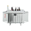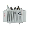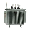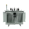

The power supply and distribution method for distribution transformers constitutes a comprehensive technical system that draws power from a high-voltage grid, transforms the voltage, and distributes electrical energy to end-users. Its core components can be categorized into two main segments: high-voltage power supply methods and low-voltage power distribution methods.
High-Voltage Side Power Supply Methods
10kV is the most common high-voltage supply level for domestic distribution transformers, typically operating on a three-phase, three-wire system with an ungrounded neutral point. Common supply modes include:
- Single-Radial Supply: The dominant mode in rural areas; a single 10kV line directly serves multiple distribution transformers. It features simple wiring, low investment costs, and limits the impact of faults to a small area.
- Multi-Sectional Supply with Moderate Interconnection: The dominant mode in urban areas; main lines are segmented with switches, and interconnection points are reserved between different lines. This allows for rapid load transfer during faults, significantly enhancing power supply reliability.
- Single/Three-Phase Hybrid Supply: Designed for dispersed rural residential loads, this method utilizes small-capacity single-phase transformers to shorten the supply radius and reduce line losses; single-phase transformer capacity does not exceed 50kVA.
- Direct Distribution (Step-Down) Supply: Used in remote areas requiring long-distance supply; a 35kV/0.4kV direct step-down mode is employed, eliminating the intermediate 10kV stage, making it suitable for scenarios with low load density.
Low-Voltage Side Power Distribution Methods
The low-voltage side uniformly outputs 380V/220V three-phase, four-wire power. Based on wiring and distribution structure, these methods fall into two categories:
1. Classification by Grounding Type (IEC Standards)
- TN System: The distribution transformer's neutral point is directly grounded, and the exposed conductive parts of the equipment are connected to this grounding point via a PE (protective earth) conductor. Sub-types include TN-C (N and PE conductors combined), TN-C-S (combined in certain sections), and TN-S (N and PE conductors completely separated; the standard for civil buildings).
- TT System: The distribution transformer's neutral point is grounded independently, and the exposed parts of the equipment are connected to a separate grounding electrode, with no electrical connection to the system's grounding point. Widely used in rural distribution areas, this system requires the installation of a residual current device (RCD) at the load end.
- IT System: The system itself is not directly grounded, while exposed conductive parts of the equipment are uniformly grounded. It offers extremely high power supply continuity and is commonly used in environments with stringent safety requirements, such as hospital operating rooms and mines.
2. Classification by Power Distribution Structure
- Radial Distribution: Power is supplied directly and independently from the low-voltage distribution room to high-capacity, critical loads. Circuits do not interfere with one another, ensuring high reliability; this method is suitable for applications such as large motors and fire-fighting equipment.
- Trunk (Busway) Distribution: A single main feeder distributes power sequentially to multiple adjacent, low-capacity loads. This saves on cabling costs and is suitable for applications like floor lighting in multi-story buildings and groups of standard low-power outlets.
- Daisy-Chain Distribution: Multiple low-capacity devices located in close proximity are connected in series on the same circuit. Limitations apply - no more than five devices and a total capacity not exceeding 10 kW per circuit - making this method suitable only for minor terminal loads.