


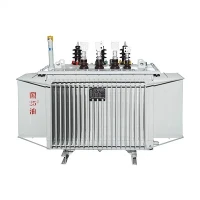
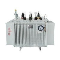
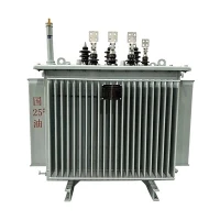
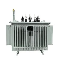
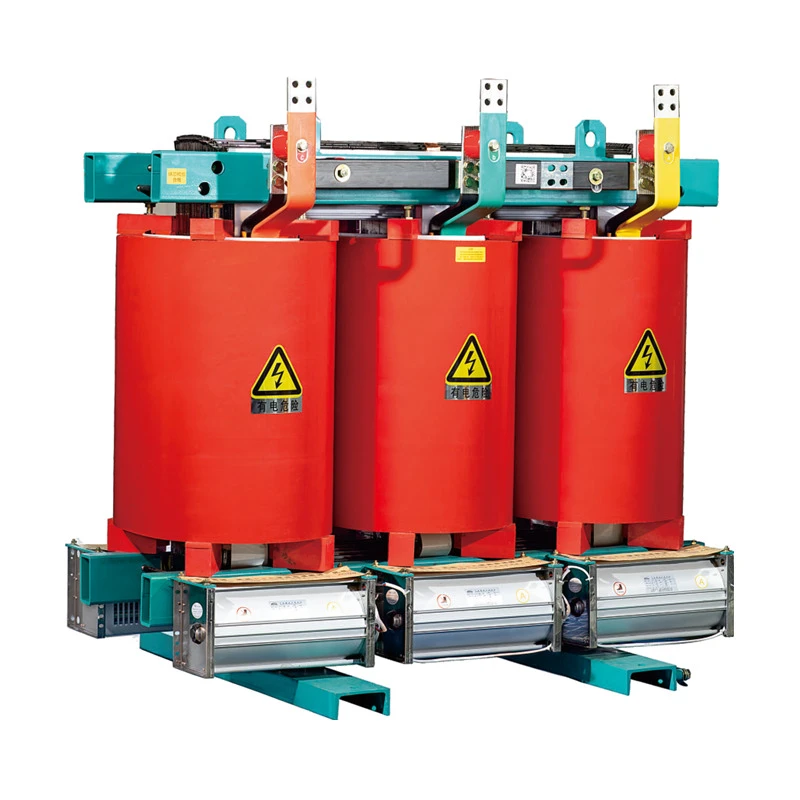
SCB Series Resin-Cast Dry-Type Step-Up Transformers
Zhejiang Tianrun Electric Co., Ltd. is one of the leading manufacturers and suppliers of scb series resin-cast dry-type step-up transformers in China. We are committed to providing high quality customized products with competitive price. We warmly welcome you to buy bulk advanced scb series resin-cast dry-type step-up transformers from our factory. Also, quotation is available.
Product Overview
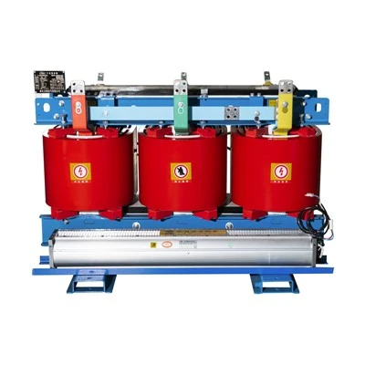
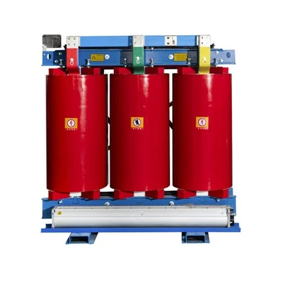
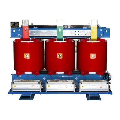
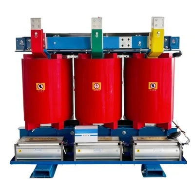
The SCB series are three-phase, epoxy-resin cast dry-type step-up transformers (B = foil-wound LV winding). They are used for grid connection of photovoltaic plants, wind farms, energy storage stations and distributed generation, stepping up the inverter/PCS output (0.4/0.8/1.14 kV, etc.) to 10 kV or 35 kV. The windings are vacuum-cast in epoxy resin and the transformer contains no oil; manufacture follows IEC 60076-11:2018 and IEC 60076-1:2011. Parameters in this catalog are typical values; final specifications are subject to the technical agreement.

Product Features
Oil-free
Windings fully encapsulated in epoxy resin; no oil or harmful gas during operation, suitable for fire-safe, oil-free locations; smaller volume than oil-immersed at the same rating.
HV windings
Vacuum-cast in filled epoxy resin with glass fibre grid reinforcement; sudden short-circuit withstand verified per the IEC 60076-11 short-circuit test.
LV windings
Foil-wound for uniform ampere-turn distribution, DMD prepreg cured as a whole; axial cooling ducts improve heat dissipation.
Core
Low-loss cold-rolled silicon steel, fully mitered joints, F-class weftless banding, resin-varnish sealed against moisture and rust; lower no-load loss and noise.
Temperature control and cooling
Intelligent controller (fault/over temperature alarm, over temperature trip, history recording) with RS485 for remote monitoring; up to 140% of rated load under forced-air cooling (ambient-dependent, per technical agreement).
Manufacturing
Vacuum drying before casting; controlled curing process; partial discharge measured per IEC 60076-11.
Type Designation

Technical Parameter
|
Item |
Value |
|
Rated frequency |
50 Hz (60 Hz on request) |
|
Phases |
3 |
|
Insulation class |
F (155); H available |
|
Cooling |
AN (natural) / AF (forced air) |
|
Vector group |
Dyn11 (Yd11 available for 35 kV power transformers) |
|
Tapping range |
±2×2.5% |
|
Insulation levels |
10 kV class: LI 75 kV / AC 35 kV; 35 kV class: LI 200 kV / AC 85 kV (per IEC 60076-3:2013) |
|
Temperature rise limits |
Class F: average winding 100 K, hot-spot 120 K (per IEC 60076-11:2018) |
|
Sound level |
Measured per IEC 60076-10:2016 |
|
Protection degree |
IP00 without enclosure; IP20/IP23 enclosure on request |
|
Installation |
Indoor mainly; altitude ≤1000 m, corrected per IEC 60076-1 for higher sites |
|
Manufacturing standards |
IEC 60076-1:2011, IEC 60076-11:2018; energy efficiency assessment per IEC 60076-20:2017 |

Environment Condition
Altitude: not exceeding 1000m.
Ambient temperature: maximum +40℃
Average temperature of the hottest month +30℃
Maximum annual average +20℃
Outdoor minimum -25℃
Supply voltage waveform approximately sinusoidal; three-phase voltages approximately symmetrical.
Installation site without obvious pollution.
Seismic ground acceleration: horizontal less than 3 m/s², vertical less than 1.5 m/s².
Special conditions beyond the normal service conditions above shall be stated at the time of inquiry and order.
Applications
Photovoltaic plants
Step-up to 10 kV for distributed projects; step-up to 35 kV in skid-mounted substations or transformer rooms for centralized projects.
01
Wind farms
Unit step-up for onshore wind (690 V or 0.4 kV → 35 kV).
02
Energy storage stations
Step-up after PCS output to 10/35 kV.
03
Other fire-safe, oil-free applications
High-rise buildings, data centers, industrial distribution.
04
Proccess of Transformer
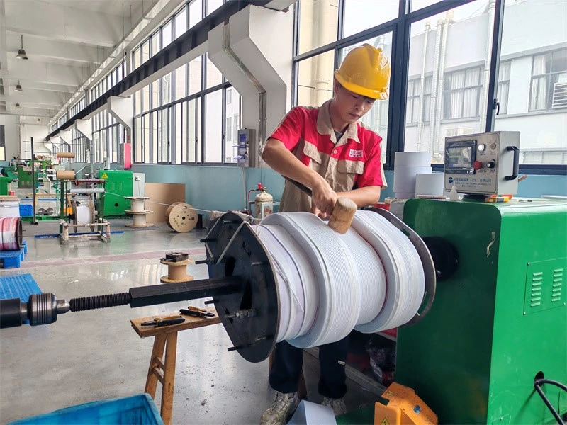
1-Wire‑wound winding of transfomer
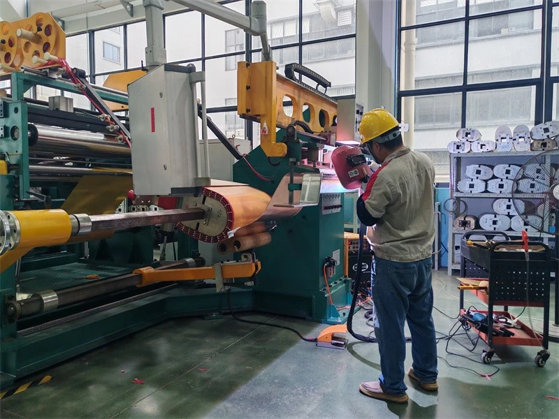
2-Foil‑wound winding of transfomer
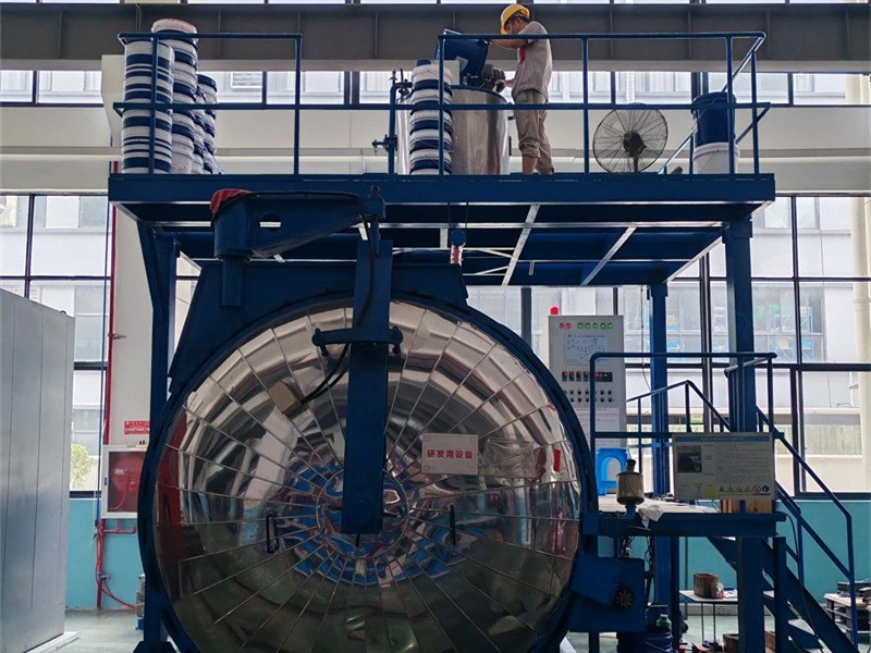
3-Vacuum casting of transformer
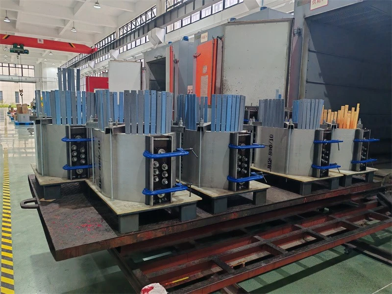
4-Epoxy resin casting of transfomer
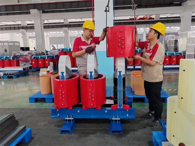
5-Coil assembling over core
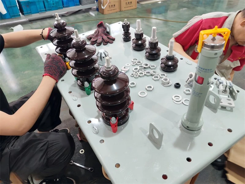
6-HV porcelain bushings of oil immersed transformer
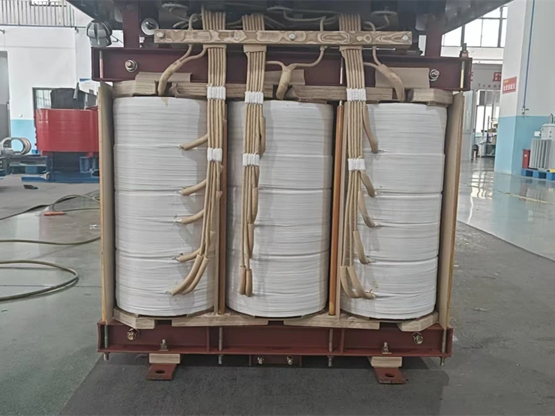
7-Lead insulation taping and welding of transfomer
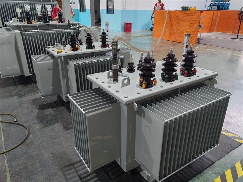
8-Vacuum oil filling of transformer
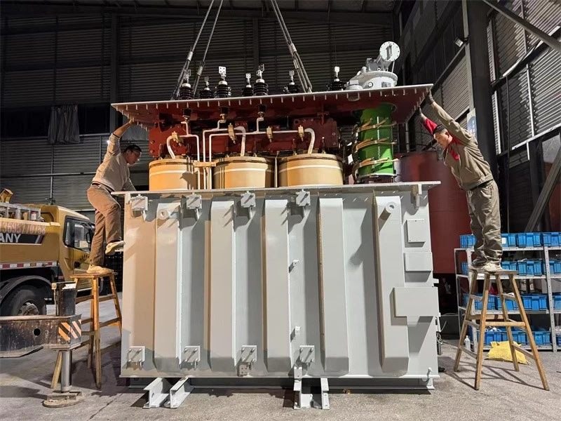
9-Tank sealing of transformer
Testing of Transformer
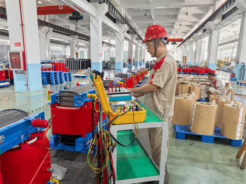
1-Measurement of winding resistance testing of transformer
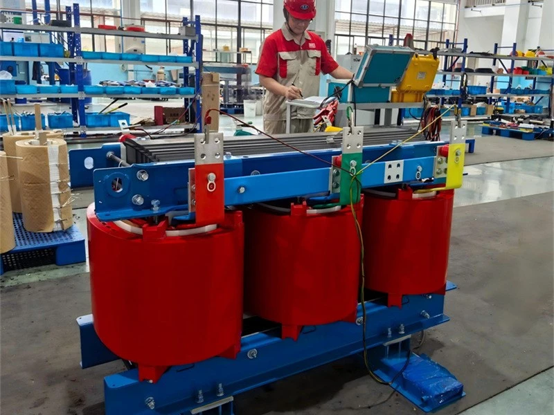
2-Measurement of voltage ratio and check of phase displacement testing of transformer
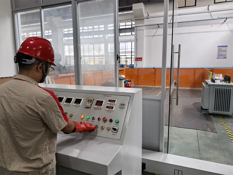
3-Separate‑source AC withstand voltage testing of transformer
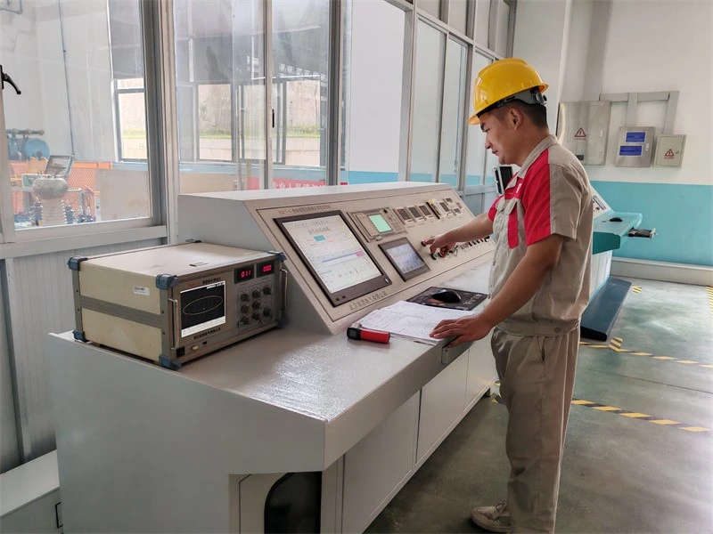
4-Measurement of no‑load loss and no‑load current of transformer
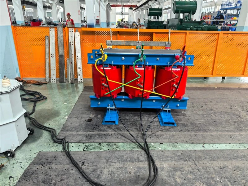
5-Measurement of short‑circuit impedance and load loss of transformer
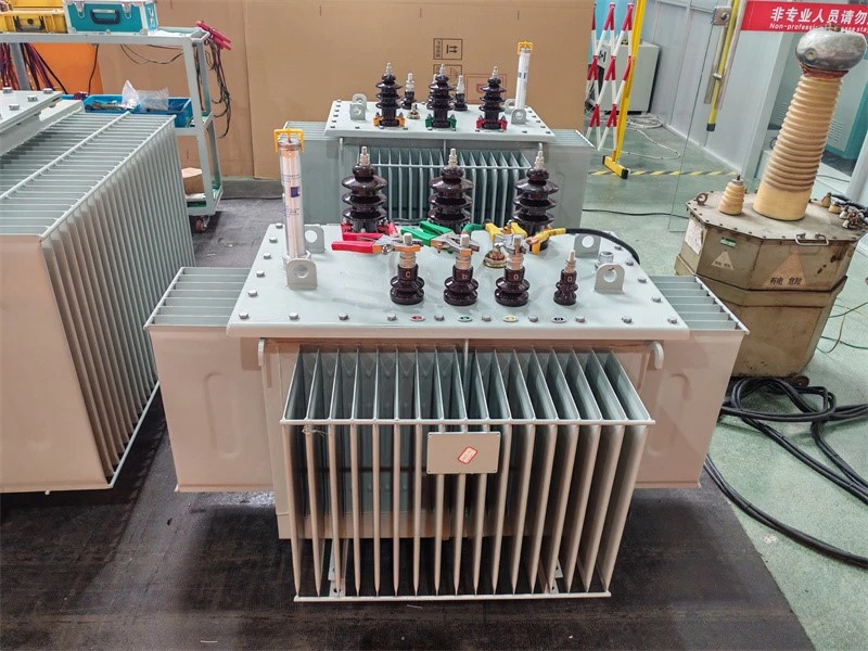
6-No load loss and no load current testing of transformer
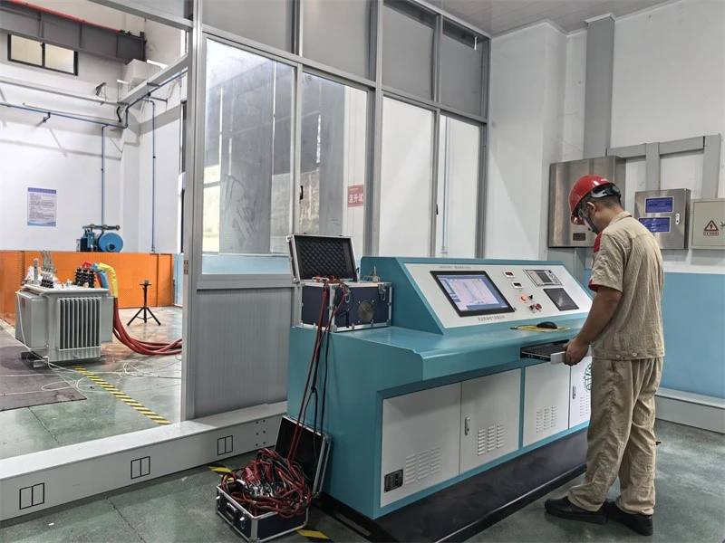
7-Temperature‑rise test of transformer
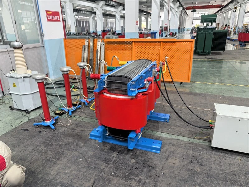
8-Partial‑discharge measurement of transformer
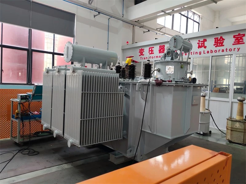
9-Winding ressitant and voltage ratio testing of transformer
FAQ
Q: How is the step-up transformer made?
It works by electromagnetic induction: AC current in the primary creates an alternating flux in the core, and the induced voltage in the secondary is proportional to the turns ratio (U2/U1 = N2/N1). With more turns on the secondary, the voltage is stepped up. For this SCB series, production covers winding, vacuum drying, epoxy casting and curing, assembly and routine tests; each unit is tested in accordance with IEC 60076-11.
Q: How does the step-up transformer work?
It works by electromagnetic induction. AC current in the primary winding sets up an alternating flux in the core, which links the secondary winding and induces a voltage in it. The induced voltage is proportional to the turns ratio: with more turns on the secondary than the primary, the output voltage is higher than the input (U2 ≈ U1 × N2/N1). As the voltage steps up, the current reduces correspondingly (power is approximately conserved), which suits feeding power into a higher-voltage grid.
Q: Is a current transformer a step-up transformer?
No. A CT transforms current in proportion and provides isolation, not voltage step-up. Its secondary has far more turns, but operates near short-circuit; opening the secondary would produce dangerously high voltage, so it must never be opened in service.
Hot Tags: scb series resin-cast dry-type step-up transformers, China scb series resin-cast dry-type step-up transformers manufacturers, suppliers, factory
Next
No InformationYou Might Also Like

Send Inquiry