


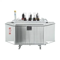
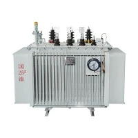
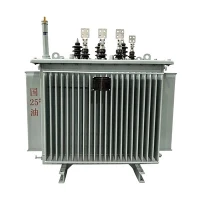
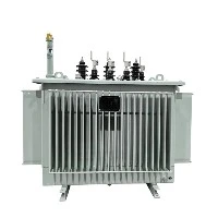
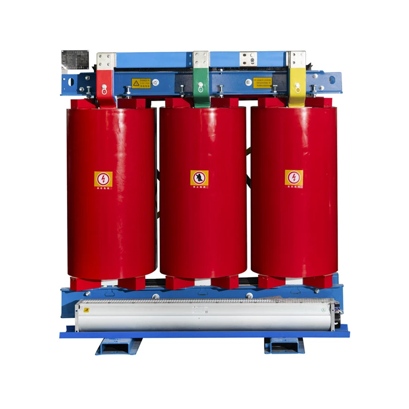

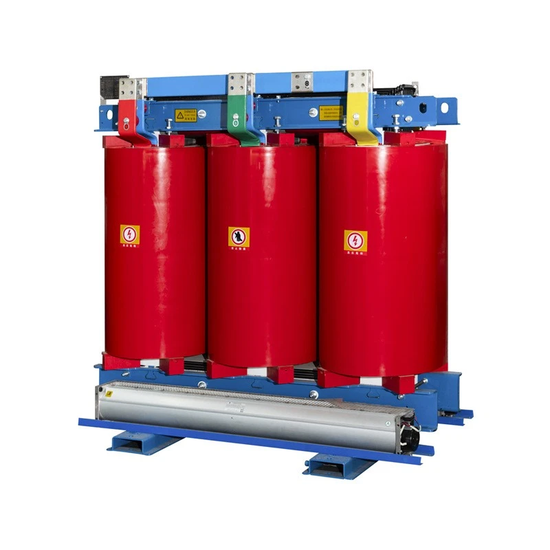
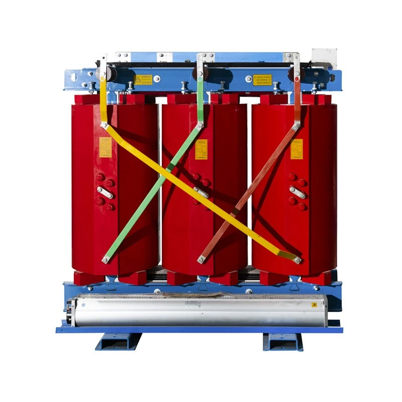
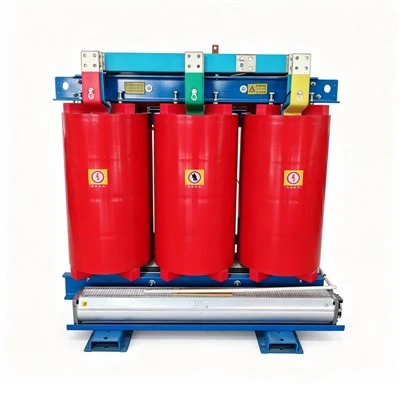
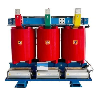
33kV Dry Type Three Phase Transformer
Rated Power: Up to 6300kVA (Customized)
Primary Voltage: 6kV, 6.3kV, 6.6kV, 10kV, 10.5kV, 11kV, 20kV, 22kV (Customized)
Secondary Voltage: 0.4kV, 0.8kV, etc. (Customized)
Tap Range: ±2×2.5%, ±5% (Customized)
Vector Group: Dyn11, Yyn0 (Customized)
Frequency: 50Hz, 60Hz (Customized)
Phase: 3 phase
Zhejiang Tianrun Electric Co., Ltd. is one of the leading manufacturers and suppliers of 33kv dry type three phase transformer in China. We are committed to providing high quality customized products with competitive price. We warmly welcome you to buy bulk advanced 33kv dry type three phase transformer from our factory. Also, quotation is available.
Product Overview
The SCB13 is the mainstream balanced high-efficiency dry-type transformer widely adopted in global mid-to-high-end overseas projects, fully complying with IEC international high-efficiency standards. It adopts ultra-high permeability silicon steel core and precision laminated magnetic circuit, with electromagnetically optimized winding structure to reduce both no-load and load loss. Vacuum cast HV coils and foil-wound LV coils ensure high insulation strength, low partial discharge and outstanding short-circuit and harmonic resistance. With standard intelligent temperature control, optional automatic cooling fans and IP protection enclosures, it features flame retardancy, zero leakage and maintenance-free operation. Suitable for 50/60Hz global complex grid environments, it delivers stable energy-saving performance, low noise and high operational reliability, becoming the preferred standard model for overseas commercial, industrial and public infrastructure projects.

Core Exclusive Advantages
Dual Energy-saving Optimization for No-load and Load Conditions
This transformer adopts dual electromagnetic optimization for both no-load and load loss. It maintains consistent and stable energy-saving performance throughout standby, light-load and full-load operating states, effectively reducing overall power consumption under variable working conditions and achieving full-cycle energy efficiency for long-term operating projects.
Outstanding Harmonic and Impact Load Resistance
With optimized core and winding structure, the equipment possesses strong resistance to harmonic distortion and sudden impact loads. It perfectly adapts to complex modern industrial scenarios equipped with a large number of frequency converters, rectifiers and other nonlinear load devices, avoiding abnormal heating and unstable power quality caused by current distortion.
Advanced Vibration and Noise Reduction Structure
Adopting professional vibration damping and noise suppression structural design, the transformer minimizes operating vibration and noise. It maintains ultra-low noise level during long-term continuous operation, fully applicable to densely populated and environmentally sensitive indoor areas such as commercial buildings, medical institutions and residential supporting facilities.
Balanced Comprehensive Performance
The product achieves flawless balanced performance covering energy efficiency, operational safety, mechanical stability and long service life. All core technical indicators meet international high-standard specifications, which can fully satisfy the rigorous assessment and application requirements of most high-end overseas commercial, public and industrial projects.
Meaning of product model

Note: More technical parameters of the transformer can not be reflected in the model, more information is required to check the technical parameters.


Product Parameter
Technical Parameter Table of 6kV, 10kV 30kVA ~ 2500kVA Non-exciting Voltage Regulating Distribution Transformer
|
Rated capacity (kVA) |
Voltage combination and tap range |
Vector group |
No-load loss (W) |
Load-loss (W) |
No-load current (%) |
Short-circuit impedance (%) |
||
|
High voltage (kV) |
High voltage tap range (%) |
Low voltage (kV) |
||||||
|
30 |
6 6.3 6.6 10 10.5 11 20 22 |
±5% ±2x2.5% |
0.4 |
Dyn11 Yyn0 |
135 |
640 |
2.0 |
4.0 |
|
50 |
195 |
900 |
2.0 |
|||||
|
80 |
265 |
1240 |
1.5 |
|||||
|
100 |
290 |
1410 |
1.5 |
|||||
|
125 |
340 |
1660 |
1.3 |
|||||
|
160 |
385 |
1910 |
1.3 |
|||||
|
200 |
445 |
2270 |
1.1 |
|||||
|
250 |
515 |
2480 |
1.1 |
|||||
|
315 |
635 |
3120 |
1.0 |
|||||
|
400 |
705 |
3590 |
1.0 |
|||||
|
500 |
835 |
4390 |
1.0 |
|||||
|
630 |
935 |
5360 |
0.85 |
6.0 |
||||
|
800 |
1090 |
6260 |
0.85 |
|||||
|
1000 |
1270 |
7310 |
0.85 |
|||||
|
1250 |
1500 |
8720 |
0.85 |
|||||
|
1600 |
1760 |
10500 |
0.85 |
|||||
|
2000 |
2190 |
13000 |
0.70 |
|||||
|
2500 |
2590 |
15400 |
0.70 |
|||||
Note: The technical parameters of our transformers are for reference only. Customized solutions are available, with specifications adjustable according to project‑specific requirements.
Operating Environmental Conditions
|
Name |
Unit |
Project needs value |
|
|
Ambient temperature |
Maximum daily temperature |
℃ |
40 |
|
Minimum daily temperature |
-25 |
||
|
Maximum diurnal temperature range |
K |
25 |
|
|
Average temperature in hottest month |
℃ |
30 (or provided by the project unit) |
|
|
Maximum annual average temperature |
20 (or provided by the project unit) |
||
|
Humidity |
Average daily relative humidity |
% |
≤95 |
|
Average monthly relative humidity |
≤90 |
||
|
Height |
m |
≤1000 |
|
|
Intensity of solar radiation |
W/cm2 |
0.1 |
|
|
Maximum ice thickness |
mm |
20 |
|
|
The average maximum wind speed at 10m above the ground for 10 minutes |
m/s |
35 |
|
|
Seismic fortification capability |
Ground level acceleration |
m/s2 |
3 |
|
Safety factor for three cycles of resonance |
≥1.67 |
||
|
Installation site (indoor/outdoor) |
Confirm with project unit before supply |
||
|
Atmospheric corrosivity levels (C1/C2/C3/C4/C5/CX) |
Confirm with project unit before supply |
||
|
Protective rating of belt shell |
IP31, IP30, IP21, IP20 (or provided by the project unit) |
||
Product Application
Widely used in overseas large‑ and medium‑sized commercial complexes, shopping malls, urban landmark commercial facilities, main power distribution systems for hospitals and schools, rail transit stations, airport auxiliary buildings, light‑industrial parks, auxiliary power distribution for conventional data centers, as well as high‑end residential communities.
- Core working condition adaptability: Especially applicable to complex power‑distribution environments packed with massive intelligent equipment and nonlinear loads. It can effectively cope with harmonic interference generated by various electronic devices, guarantee stable power quality and reduce equipment overheating risks caused by distorted current.
- Project positioning: It acts as the mainstream standard choice for newly‑constructed mid‑to‑high‑end commercial, public infrastructure and industrial projects worldwide, balancing reliable operational performance, safety requirements and long‑term running stability for high‑density power‑consumption sites.
Differences among SCB10, SCB11, SCB12, SCB13, SCB14, SCB18
|
Dimension |
SCB10 |
SCB11 |
SCB12 |
SCB13 |
SCB14 |
SCB18 |
|
Core material |
Standard grain-oriented silicon steel |
Higher-grade silicon steel |
High-permeability thin-gauge silicon steel |
Optimized magnetic circuit, some use amorphous alloy |
Premium high-permeability silicon steel |
Ultra-thin high-permeability silicon steel, 3D wound core |
|
No-load loss |
Highest |
High |
Medium |
Low |
Lower |
Lowest |
|
Load loss |
Highest |
High |
Medium |
Low |
Low |
Lowest |
|
Noise level |
Loudest |
Louder |
Quiet |
Quieter |
Quieter |
Quietest |
|
No-load current |
Highest |
High |
Medium |
Low |
Lower |
Lowest |
|
Partial discharge |
Highest |
High |
Medium |
Low |
Low |
Lowest |
|
Purchase cost |
Lowest |
Lower |
Medium |
Higher |
High |
Highest |
|
Size & weight |
Most compact |
Compact |
Slightly larger |
Larger |
Larger |
Largest |
|
Typical use |
Temporary replacement of old equipment |
General industry, backup |
Budget-sensitive new projects |
Legacy retrofit, noise-sensitive |
Commercial buildings, schools, hospitals, industrial, municipal |
Data centers, financial hubs, commercial complexes, renewable energy, critical loads |
Summary: SCB10 to SCB18 form an efficiency ladder - higher numbers mean better core materials, lower losses, quieter operation, and higher upfront cost, but lower long-term operating cost.
Proccess of Transformer
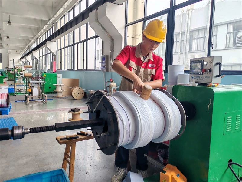
1-Wire‑wound winding of transfomer
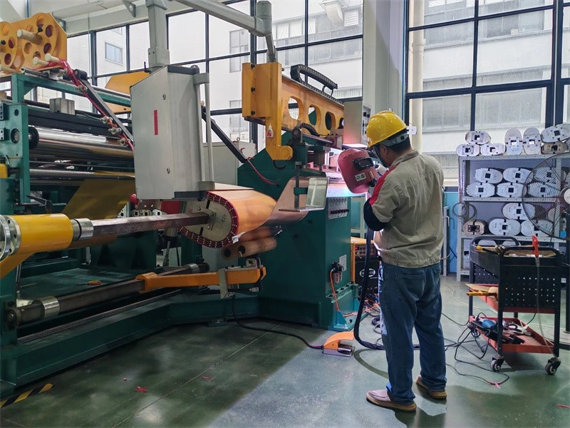
2-Foil‑wound winding of transfomer
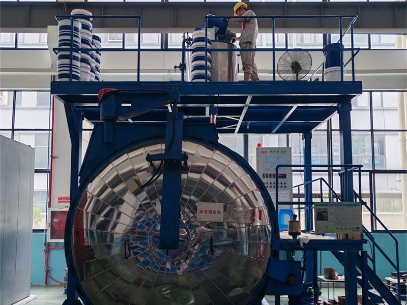
3-Vacuum casting of transformer
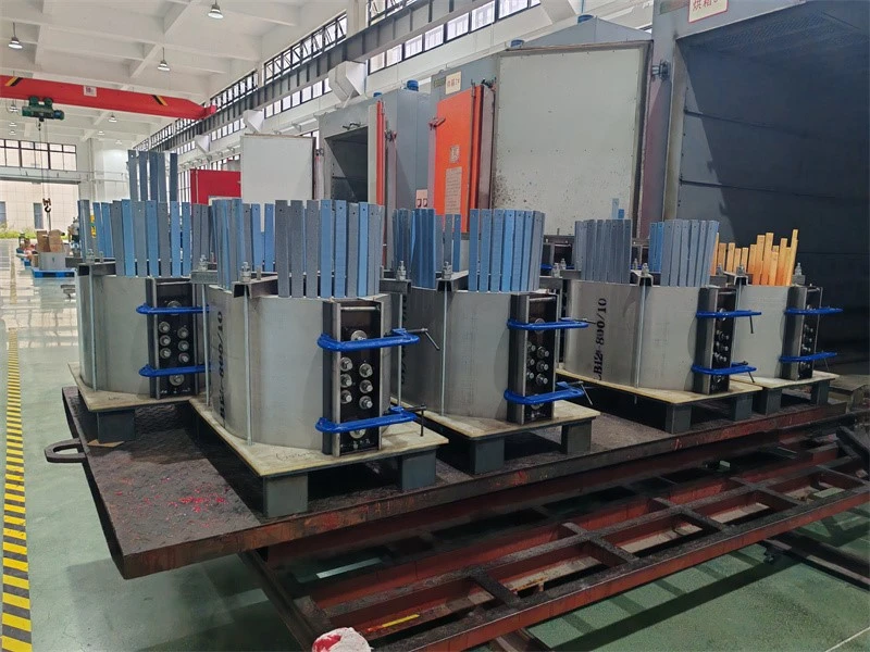
4-Epoxy resin casting of transfomer
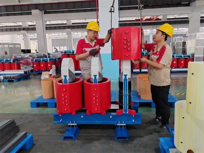
5-Coil assembling over core
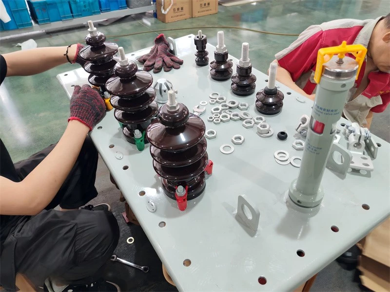
6-HV porcelain bushings of oil immersed transformer
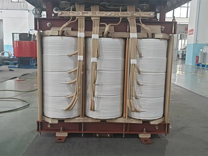
7-Lead insulation taping and welding of transfomer
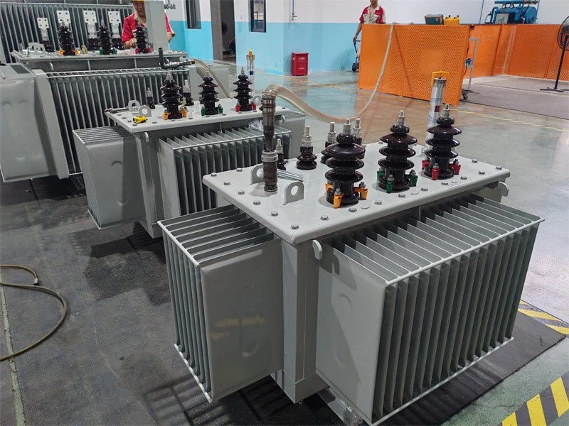
8-Vacuum oil filling of transformer
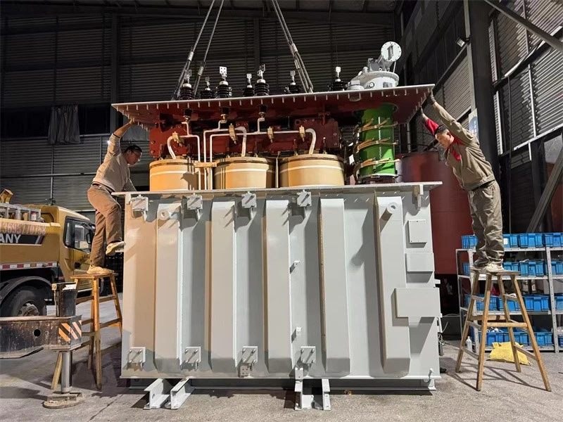
9-Tank sealing of transformer
Testing of Transformer
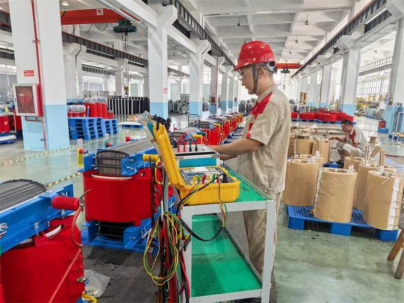
1-Measurement of winding resistance testing of transformer
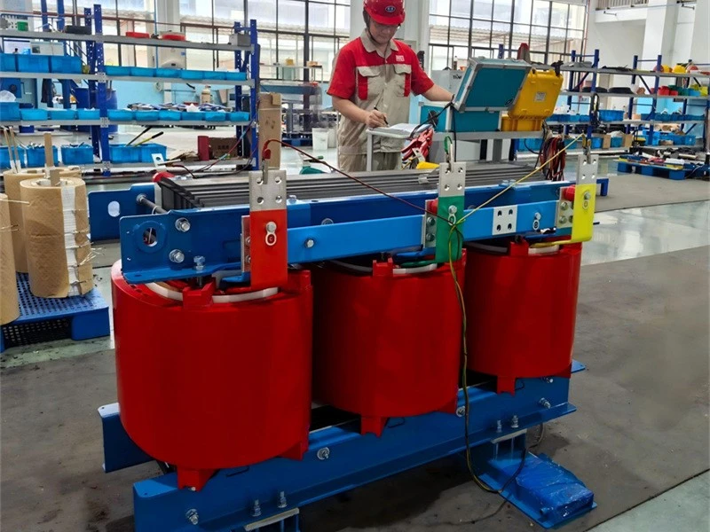
2-Measurement of voltage ratio and check of phase displacement testing of transformer
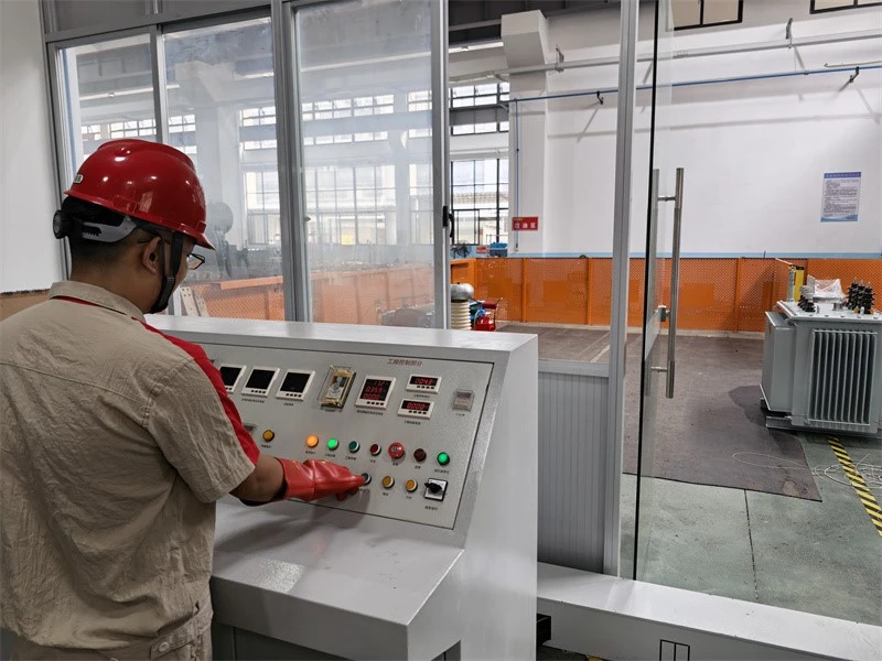
3-Separate‑source AC withstand voltage testing of transformer
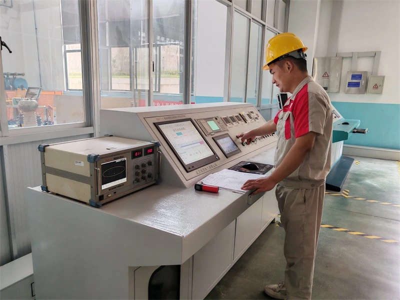
4-Measurement of no‑load loss and no‑load current of transformer
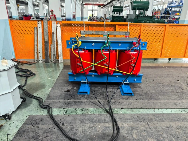
5-Measurement of short‑circuit impedance and load loss of transformer
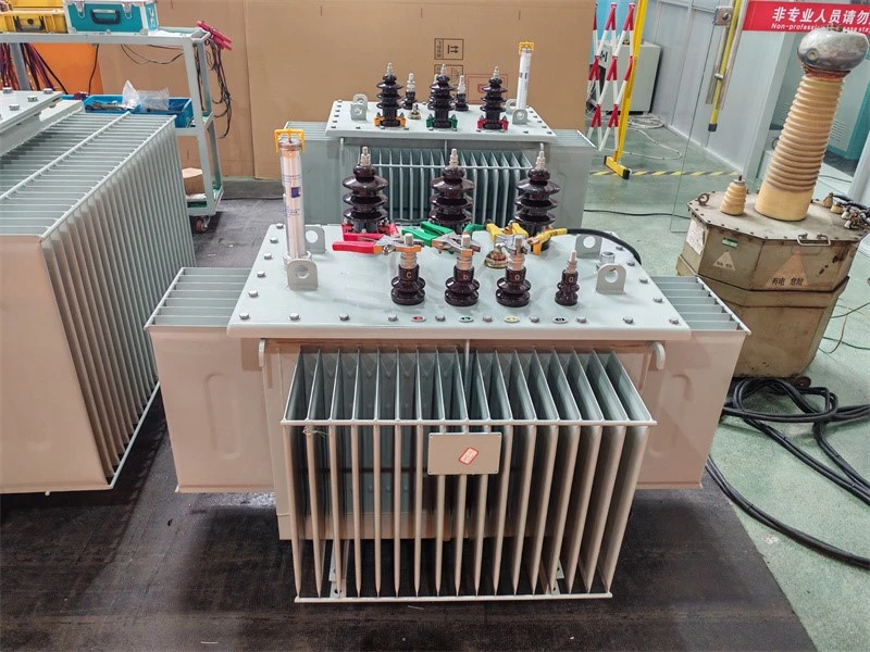
6-No load loss and no load current testing of transformer
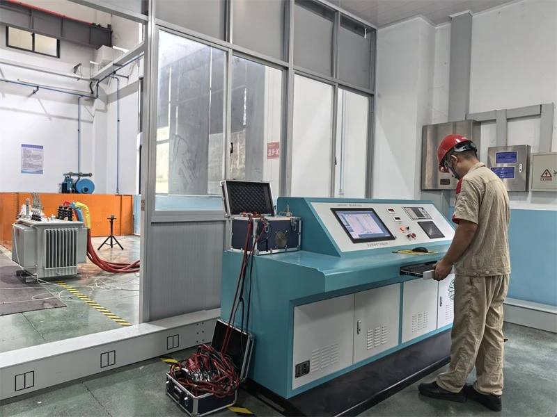
7-Temperature‑rise test of transformer
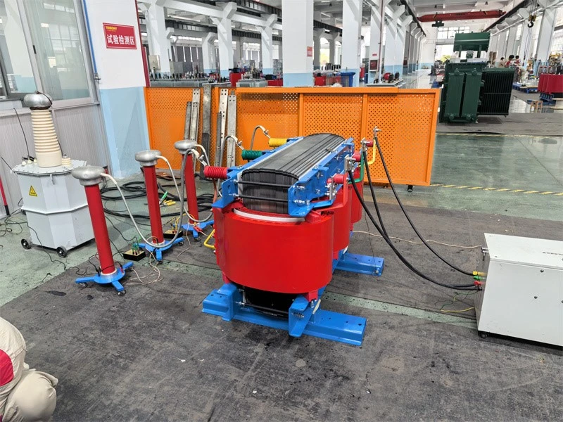
8-Partial‑discharge measurement of transformer
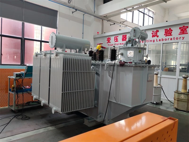
9-Winding ressitant and voltage ratio testing of transformer
FAQ
Q1: What is a dry type transformer?
A: A dry-type transformer is a transformer that uses air rather than insulating oil as its cooling and insulating medium, with windings typically cast in epoxy resin. Because it contains no oil, it eliminates the risk of flammable liquid fires and leaks, requires little maintenance, and is well suited for indoor locations such as commercial buildings, hospitals and factories. It is cooled by natural air circulation or by forced-air fans, and is widely chosen where fire safety and low maintenance are priorities.
Q2: How are dry-type transformers made?
A: Dry-type transformers are made by first stacking silicon steel sheets into a laminated core. Copper or aluminum foil is then wound into the low-voltage coil, and wire is wound into the high-voltage coil. The high-voltage coil is dried, placed in a mould, and filled with epoxy resin under vacuum, then baked until solid. The coils are fitted onto the core, clamped and wired together. Temperature sensors, fans and terminals are added, and the finished unit is electrically tested before shipping.
Q3: How does a dry-type transformer work?
A: A dry-type transformer works on the same principle as any transformer: alternating current in the primary winding creates a changing magnetic field in the laminated core, which then induces a voltage in the secondary winding. The ratio of primary to secondary turns determines whether the voltage is stepped up or stepped down. The only difference from an oil-immersed transformer is that the heat generated by the windings and core is carried away by surrounding air - either by natural convection or by forced cooling fans - rather than by circulating oil.
Hot Tags: 33kv dry type three phase transformer, China 33kv dry type three phase transformer manufacturers, suppliers, factory
You Might Also Like

Send Inquiry