


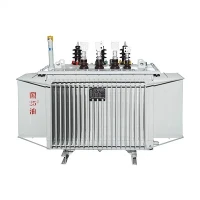
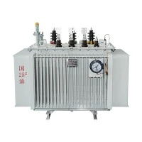
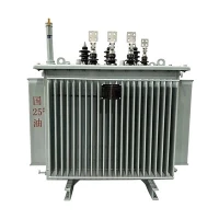
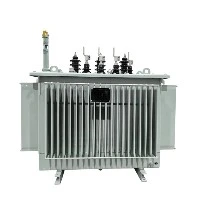
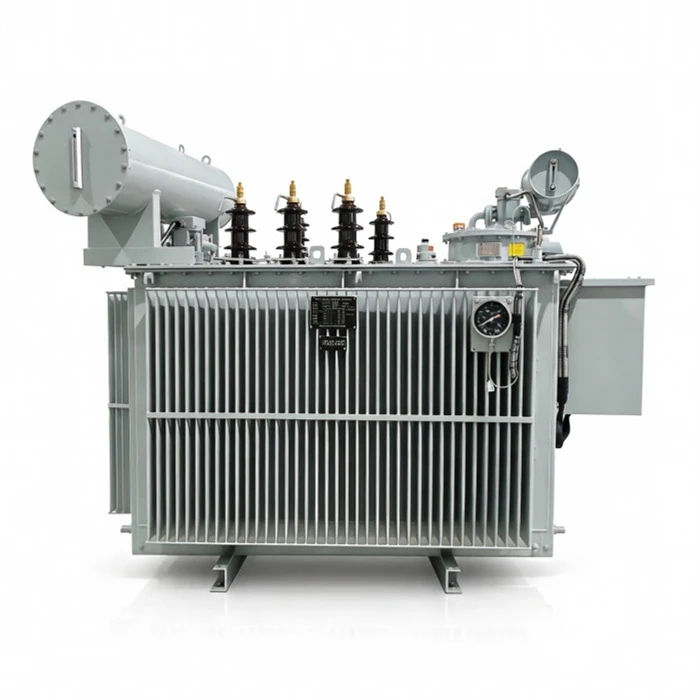

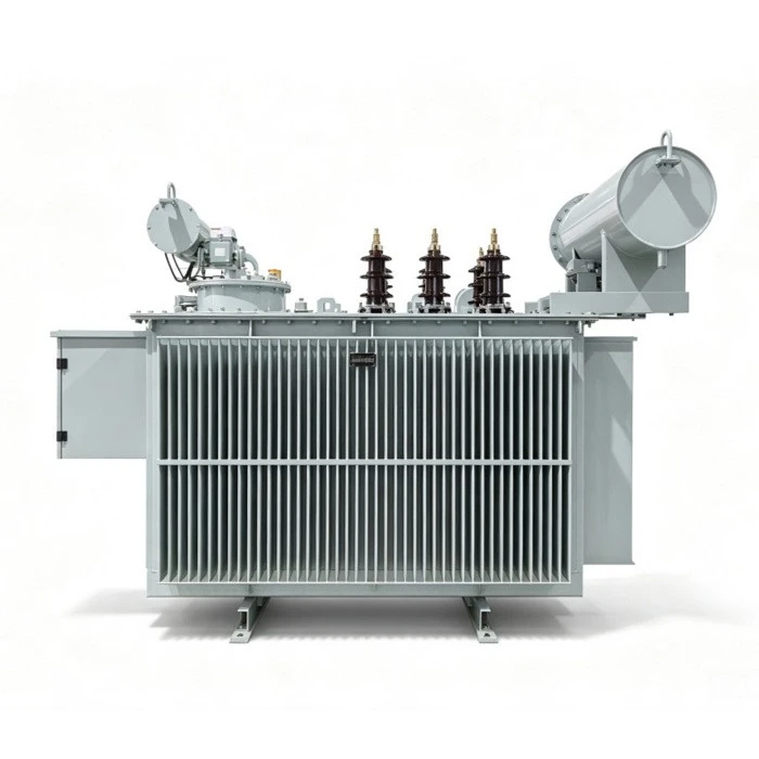
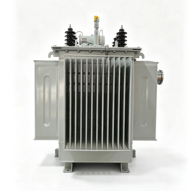
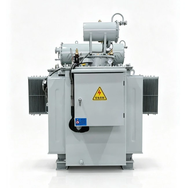
Self-coupling Voltage Regulator/ Auto Regular OLTC Transformer
Rated Power: 4,000kVA, 12,500kVA, 24,000kVA
Rated Voltage: 6kV, 10kV, 35kV
Vector Group: Ya0
Phase: 3 phase
Frequency: 50Hz
Notes: The SVR series three phase oil filled distribution transformers cover rated capacities of 4000 kVA, 12500 kVA and 24000 kVA for 6kV, 10kV, 35kV voltage classes with Ya0 vector group at 50Hz.
This series supports customised capacity, regulation range, cooling mode and protection configuration according to site specific feeder conditions.
Zhejiang Tianrun Electric Co., Ltd. is one of the leading manufacturers and suppliers of self-coupling voltage regulator/ auto regular oltc transformer in China. We are committed to providing high quality customized products with competitive price. We warmly welcome you to buy bulk advanced self-coupling voltage regulator/ auto regular oltc transformer from our factory. Also, quotation is available.
Product Overview
The SVR Series Oil-Immersed Feeder Automatic Voltage Regulator is an on-load tap-changing integrated device connected in series with 6kV–35kV distribution lines. By continuously sampling the line voltage and automatically adjusting the autotransformer ratio via the built-in on-load tap-changer, the unit stabilizes the output voltage within the preset range, effectively addressing under voltage at the remote end of long feeders and voltage excursions caused by load fluctuations.
Featuring a fully-sealed oil-immersed tank, the product inherits the inherent advantages of high cooling efficiency, strong dielectric strength and excellent short-circuit withstand capability. The mechanical on-load regulating mechanism and digital sampling control unit are integrally enclosed in the same tank, making it suitable for voltage quality improvement in rural power grids, industrial parks, mining sites and long-distance transmission lines.

Features
Compact & Efficient
High capacity, low loss, compact footprint. Easy to install and maintain in any environment.
Auto Tap Changing
Tracks voltage variations and adjusts the 3-phase on-load tap-changer with precision and reliability.
Flexible Parameters
Adjustable voltage reference, action delay, range, and operation count limits for site customization.
Real-Time Display
Shows output voltage, current, daily/total operations, tap position, and high/low tap indicators.
Comprehensive Protection
Upper/lower tap limits, operation timing, over-current & under-voltage automatic lockout.
DSP Digital Controller
High-speed DSP with precision signal detection, strong anti-interference, and lightning protection.
Remote Communication
Short-range wireless for on-site monitoring. Optional GPRS/CDMA for remote access.
Bi-Directional Power Flow
Supports feeders with embedded small hydropower generation in both wet and dry seasons.
Proven Reliability
1,000+ units since 2003; earliest units exceed 10 years continuous safe operation.
Technical Specifications
|
Rated Power (kV) |
Vector Group |
Voltage Combination (kV) |
No-load Loss (W) |
Load Loss (W) |
No-load Current (%) |
Short-circuit Impedance (%) |
||
|
High-Voltage |
Tapping Range |
Low-Voltage |
||||||
|
2000 |
Yd11 |
35 |
±3×2.5% |
6.3 10.5 |
2300 |
19240 |
0.80 |
6.5 |
|
2500 |
2720 |
20640 |
0.80 |
|||||
|
3150 |
35~38.5 |
±3×2.5% |
6.3 10.5 |
3230 |
24710 |
0.72 |
7.0 |
|
|
4000 |
3870 |
29160 |
0.72 |
|||||
|
5000 |
4640 |
34200 |
0.68 |
|||||
|
6300 |
5630 |
36800 |
0.68 |
7.5 |
||||
|
8000 |
Ynd11 |
35~38.5 |
±3×2.5% |
6.3 6.6 10.5 11 |
7870 |
40600 |
0.60 |
|
|
10000 |
9280 |
48100 |
0.60 |
|||||
|
12500 |
10940 |
56900 |
0.56 |
8.0 |
||||
|
16000 |
13170 |
70300 |
0.54 |
|||||
|
20000 |
15570 |
82800 |
0.54 |
|||||
General Specifications
|
Parameter |
Specification |
|
Rated Voltage |
6 kV / 6.3kV / 6.6kV / 10 kV / 10.5kV / 11kV / 22kV / 33kV / 35 kV |
|
Rated Capacity |
≤ 4,000 kVA (6 kV) / ≤ 12,500 kVA (10 kV) / ≤ 24,000 kVA (35 kV) |
|
Number of Phases |
3 |
|
Rated Frequency |
50Hz / 60Hz |
|
Cooling Method |
ONAN (Oil Natural Air Natural) |
|
Connection Symbol |
Ya0 / Ynd11 / Dyn11 (Customized) |
Voltage Regulation Ranges (10kV Example)
|
Range |
Input Voltage |
Output Voltage |
|
-10% to +10% |
9.0 kV – 11.0 kV |
10 kV |
|
-5% to +15% |
8.66 kV – 10.32 kV |
10 kV |
|
0% to +20% |
8.0 kV – 10.0 kV |
10 kV |
BSVR vs. SVR - Comparison Table
|
Item |
BSVR (Bidirectional Step Voltage Regulator) |
SVR (Step Voltage Regulator) |
|
Full Name |
Bidirectional Step Voltage Regulator |
Step Voltage Regulator |
|
Core Feature |
Regulator body and bidirectional switch integrally enclosed in the same tank |
Standalone regulator body; bidirectional disconnector is an external optional accessory |
|
Operational Safety |
Mechanical interlock between bidirectional and ground positions prevents accidental grounding of live line |
Disconnector operation relies on procedural compliance, no forced interlock |
|
Maintenance Outage |
Rotate switch to bidirectional position to isolate body without outage; groundable for safe maintenance |
Requires closing external bidirectional, then opening both side disconnectors - more steps |
|
Protection |
Some models integrate over-current, instantaneous and under-voltage protection |
Primarily voltage regulation; protection relies on upstream breaker or external devices |
|
Typical Rating |
Class 6kV ≤4,000 kVA; Class 10kV ≤12,500 kVA; Class 35kV ≤24,000 kVA |
500–24,000 kVA |
|
Regulation Range |
±10%, ±15%, ±20% (Customized - 30%~+10%) |
±10%, ±15%, ±20% (Customized 0~+20% etc.) |
|
Tap Positions |
7 / 9 |
7 / 9 |
|
Cooling |
ONAN |
ONAN |
|
Communication |
RS485 + GPRS/4G, supports telemetry/telesignal/telecontrol |
RS485, GPRS/4G (Opention) |
|
Typical Application |
Feeders requiring high supply continuity, minimal O&M staff, simplified installation and operation |
General feeder voltage regulation where bidirectional and protection are already provided at the substation/switchyard |
|
Cost |
Higher (integrated design) |
Lower (body-only pricing) |
|
O&M Complexity |
Low - integrated design, fewer inspection points, standardized operation |
Medium - requires maintaining both body and external disconnector |
Application Areas
- Rural Distribution: Long-distance rural feeders with voltage drop
- Urban Distribution: City network voltage quality improvement
- Oil Fields: Remote well pumping stations
- Coal Mining: Underground & surface mining operations
- Metallurgy & Chemical: Industrial plants with sensitive equipment
- Disaster Relief: Yushu earthquake airport pwer supply (2010)
Operating Principle
The regulator adopts an auto-transformer topology: the series winding is connected in series with the line, while the exciting winding is connected to the system through the on-load tap-changer. The controller continuously monitors the output voltage. When the voltage deviates from the target value beyond the preset delay, it drives the tap-changer to switch positions, altering the polarity and magnitude of the induced EMF in the series winding to achieve step-up or step-down regulation - all without interrupting the load.
Proccess of Transformer
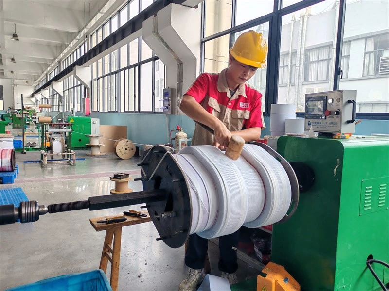
1-Wire‑wound winding of transfomer
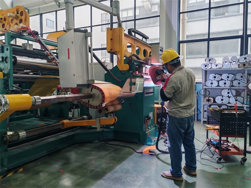
2-Foil‑wound winding of transfomer
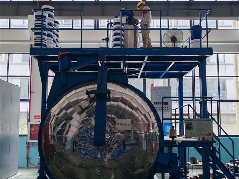
3-Vacuum casting of transformer
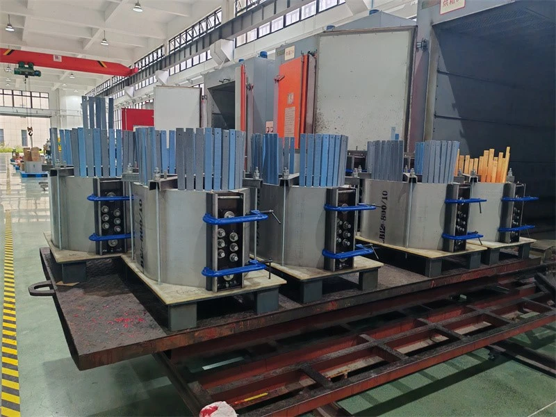
4-Epoxy resin casting of transfomer
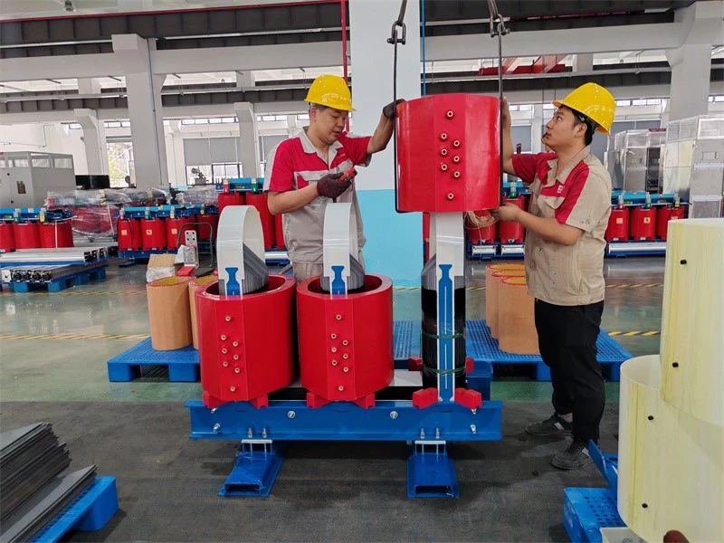
5-Coil assembling over core
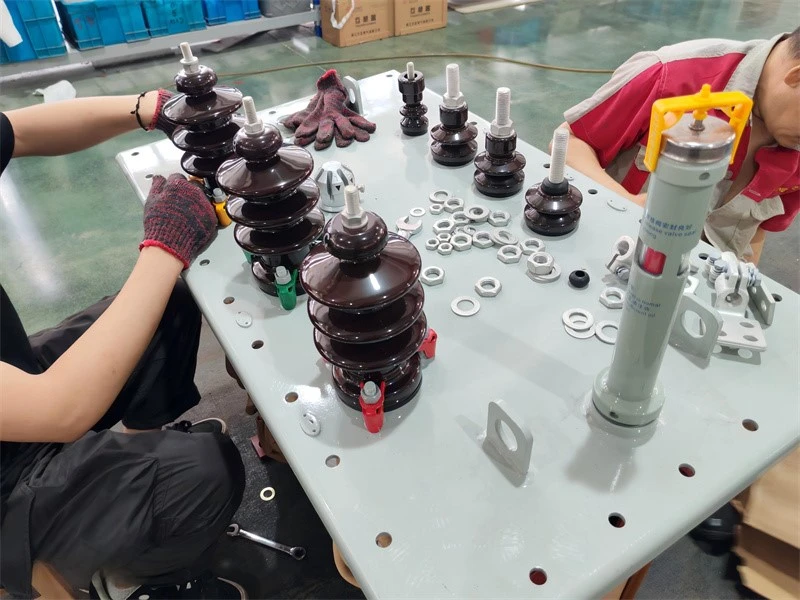
6-HV porcelain bushings of oil immersed transformer
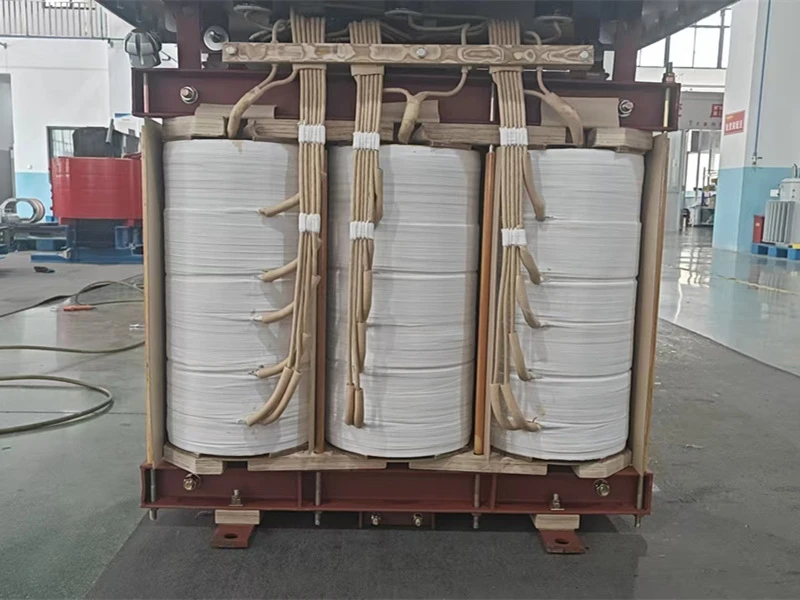
7-Lead insulation taping and welding of transfomer
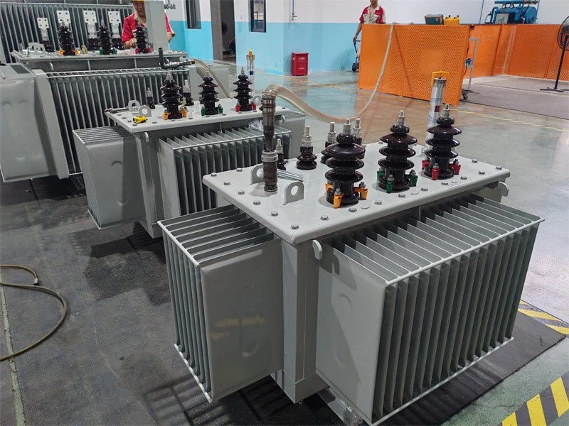
8-Vacuum oil filling of transformer
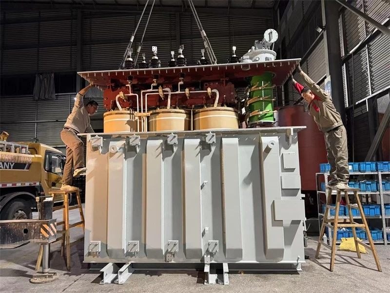
9-Tank sealing of transformer
Testing of Transformer
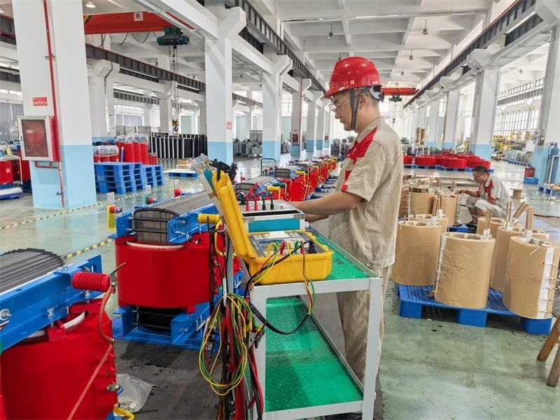
1-Measurement of winding resistance testing of transformer
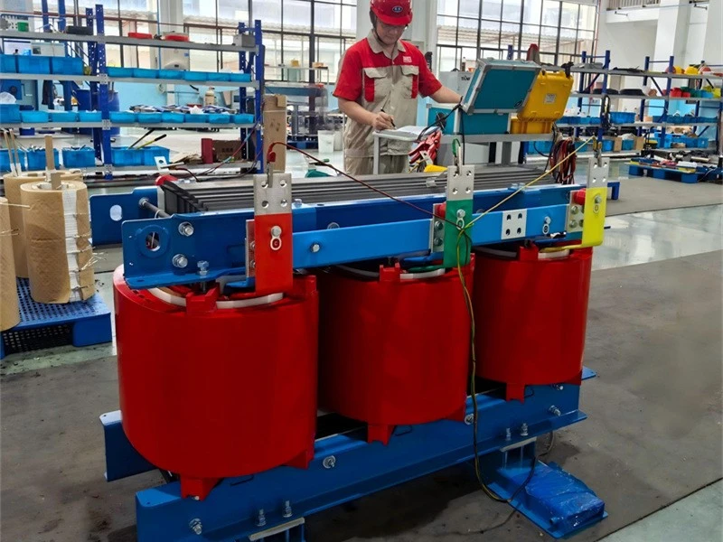
2-Measurement of voltage ratio and check of phase displacement testing of transformer
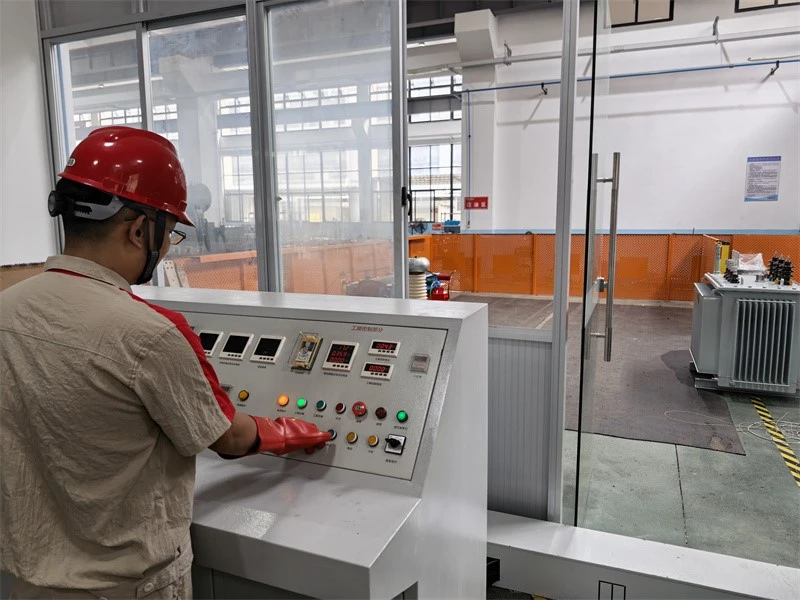
3-Separate‑source AC withstand voltage testing of transformer
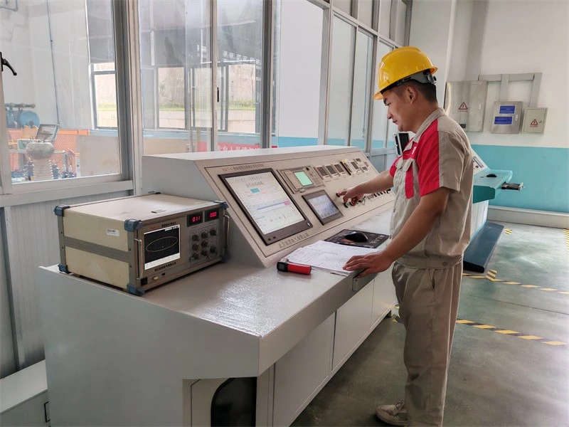
4-Measurement of no‑load loss and no‑load current of transformer
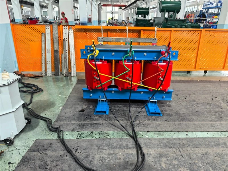
5-Measurement of short‑circuit impedance and load loss of transformer
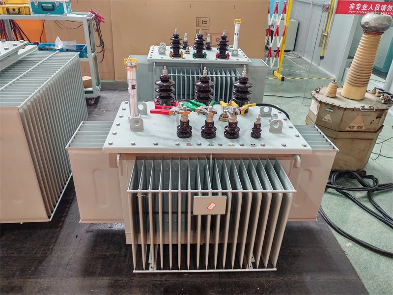
6-No load loss and no load current testing of transformer
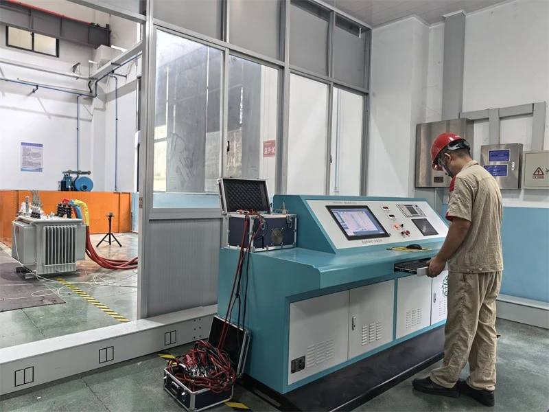
7-Temperature‑rise test of transformer
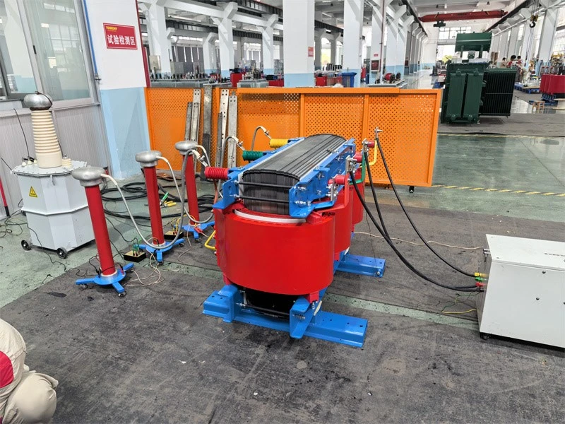
8-Partial‑discharge measurement of transformer
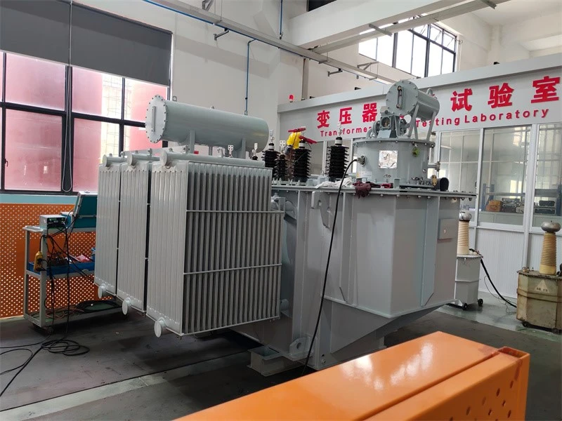
9-Winding ressitant and voltage ratio testing of transformer
FAQ
Q1: What is an SVR, and how does it differ from a conventional distribution transformer?
An SVR (Step Voltage Regulator) is an on-load voltage-regulating device connected in series with a distribution line. Its core function is real-time line voltage regulation, not voltage-level conversion for power distribution. A conventional distribution transformer steps down high voltage to low voltage for end users; an SVR is inserted in series with the feeder and automatically adjusts its ratio via an on-load tap-changer to keep the line voltage within the qualified range - it does not perform distribution step-down.
Q2: What is the voltage regulation range? Can it be customized?
Standard regulation ranges are ±10%, ±15% and ±20%, corresponding to 7 or 9 tap positions. Custom ranges such as 0~+20% (boost-only) or -30%~+10% are available, with up to 16 tap positions. The selection should be based on the maximum feeder voltage drop, load fluctuation amplitude and target voltage at the remote end.
Q3: Will the power supply be interrupted during tap changing?
No. The SVR uses an on-load tap-changer that performs tap transitions under load within milliseconds, ensuring uninterrupted power supply.
Q4: How do I determine whether an SVR is needed on a feeder?
Consider installing an SVR when: ① the voltage at the remote end of a long feeder drops below 93% of rated value (0.93 p.u.); ② load fluctuations cause under voltage during peak hours and overvoltage during off-peak hours; ③ distributed generation interconnection causes reverse voltage excursions; ④ customer-side equipment is voltage-sensitive (e.g., precision manufacturing, data centers). A load-flow calculation or measured voltage profile is recommended before determining the installation location and rating.
Q5: How is the SVR rating selected?
The SVR rated capacity should be no less than the maximum through-load at the installation point, with a 15%–20% margin. Note that the SVR rating refers to the through-capacity of its series winding, not the total system capacity. Common ratings include 630, 1000, 1250, 2000, 3150, 4000 and 6300 kVA; the 35kV class can reach up to 24,000 kVA.
Q6: Does the SVR require routine maintenance? What is the maintenance interval?
The fully-sealed oil-immersed SVR is maintenance-free in daily operation. An outage inspection every 3–5 years is recommended, including: oil dissolved-gas analysis (DGA), tap-changer operation count check, insulation resistance test, seal visual inspection and fastener re-torqueing. The on-load tap-changer should be overhauled or replaced after reaching its electrical life (≥50,000 operations).
Q7: Does the SVR support remote monitoring?
Yes. The controller is equipped with a standard RS485 interface (Modbus-RTU), and an optional GPRS/4G wireless module is available. It can integrate with distribution automation systems (SCADA/DMS) for voltage telemetry, tap-position telesignal, remote tap adjustment and fault alarm reporting.
Hot Tags: self-coupling voltage regulator/ auto regular oltc transformer, China self-coupling voltage regulator/ auto regular oltc transformer manufacturers, suppliers, factory
Next
No InformationYou Might Also Like
Send Inquiry