


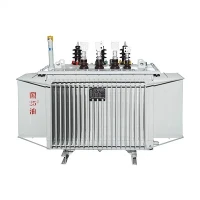
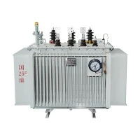
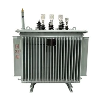
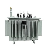
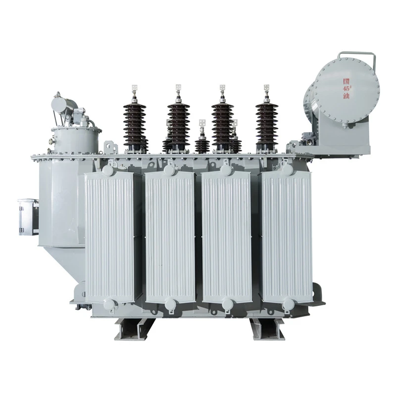

On-load Tap Changer Distribution Voltage Regulators
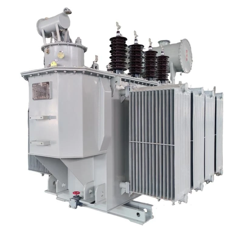
On-load Tap Changer Distribution Voltage Regulators suppliers
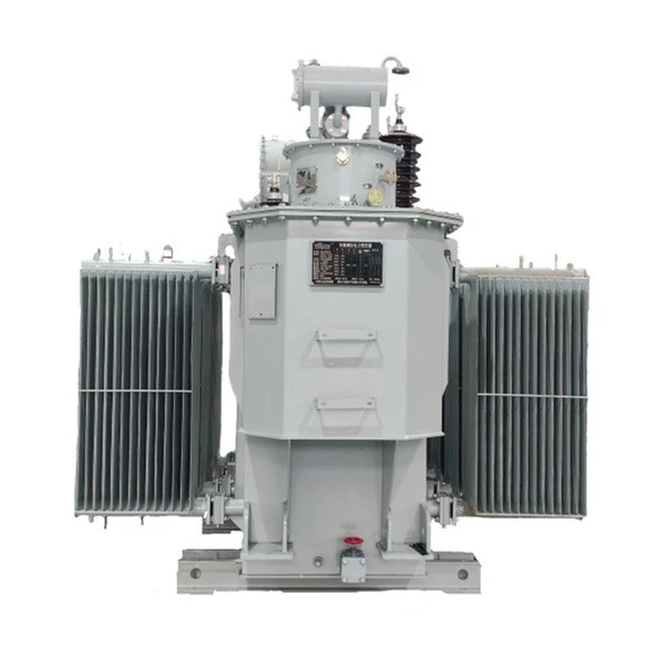
On-load Tap Changer Distribution Voltage Regulators factory
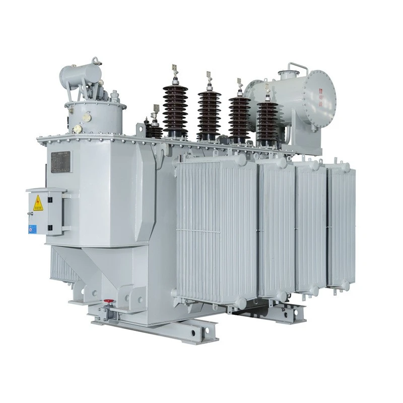
On-load Tap Changer Distribution Voltage Regulators best
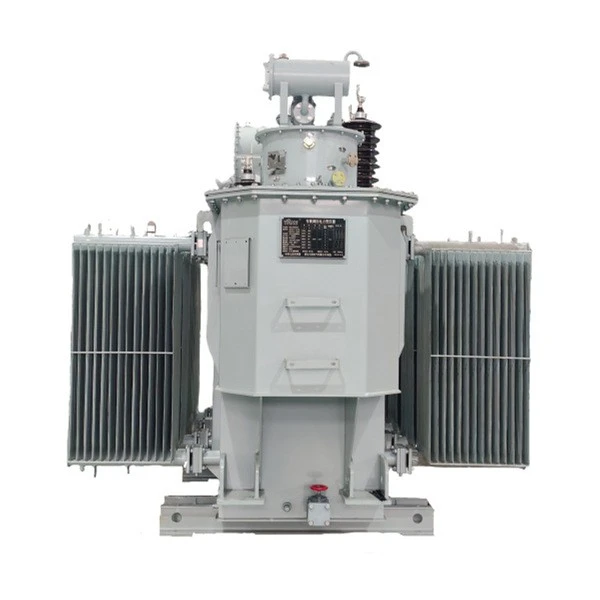
On-load Tap Changer Distribution Voltage Regulators high quality
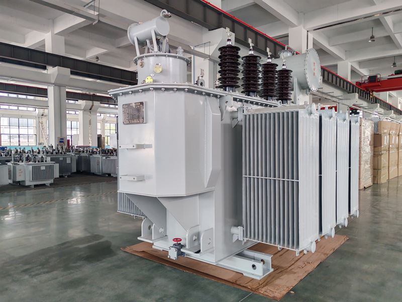
On-load Tap Changer Distribution Voltage Regulators price
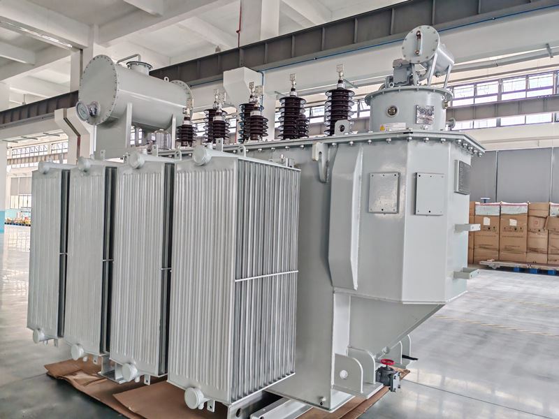
On-load Tap Changer Distribution Voltage Regulators manufacturers
On-load Tap Changer Distribution Voltage Regulators
Rated Power: 2000kVA-31500kVA (Customized)
Rated Voltage: 33~38.5kV (Customized)
Tap Range: ±3×2.5% (Customized)
Phase: 3 phase
Rated Frequency: 50HZ, 60HZ
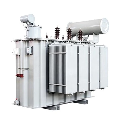
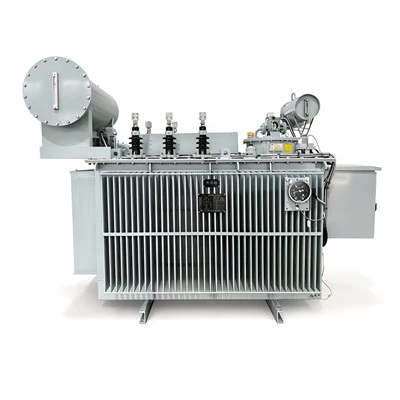
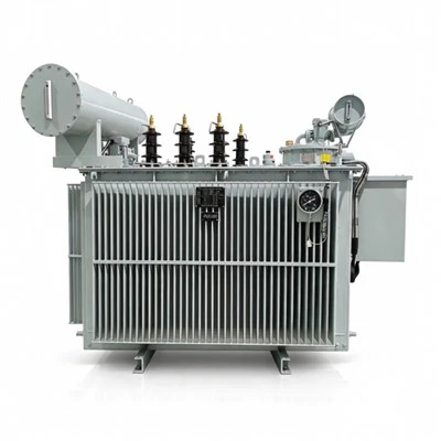
Notes: The SZ series regulation transformer is engineered for continuous voltage regulation in distribution and transmission networks, delivering stable output voltage under fluctuating load and grid conditions. As an on-load tap-changing regulation transformer, it adjusts turns ratio without interrupting power supply, making it ideal for applications requiring uninterrupted voltage control.
Zhejiang Tianrun Electric Co., Ltd. is one of the leading manufacturers and suppliers of on-load tap changer distribution voltage regulators in China. We are committed to providing high quality customized products with competitive price. We warmly welcome you to buy bulk advanced on-load tap changer distribution voltage regulators from our factory. Also, quotation is available.
Product Overview
The SZ Series Regulation Transformer is an auto-coupled on-load tap-changing main power transformer with a rated capacity of 2,000–315,000 kVA and voltage class of 33–38.5 kV (three-phase, 50/60 Hz). It features a high-permeability silicon steel core, oxygen-free copper windings, an auto-coupled common winding that reduces losses versus equivalent two-winding units, and a fully sealed oil tank for low maintenance. The on-load tap changer (±3×2.5%) allows voltage adjustment under full load without interruption; ONAN cooling is standard with ONAF optional. Manufactured to IEC 60076.
Suitable for grid substations, power plants, industrial parks, renewable energy stations, and grid tie-points. As a linking transformer between voltage levels, its on-load tap function stabilizes output amid grid fluctuations; note that its lower impedance requires short-circuit current verification at the design stage, and the neutral must be solidly earthed - it is not suitable for unearthed systems. For VFD/rectifier or renewable loads, harmonic content and low-voltage ride-through (LVRT) requirements should be confirmed against local grid codes. Voltage ratio, impedance, vector group, tap range, cooling method, and protection accessories are fully customizable to project specifications.

Core Features
Auto-coupled High Efficiency
Shared common winding reduces active material by ~15–20% vs. equivalent two-winding transformers, cutting no-load and load losses and lowering lifecycle operating cost.
On-load Voltage Stabilization
Built-in on-load tap changer (±3×2.5%) adjusts voltage ratio under full rated load in seconds - no power interruption, keeping output voltage stable through grid fluctuations and load changes.
Compact & Lightweight
Auto-coupled design delivers the same power rating in a smaller, lighter unit - saving substation space, simplifying transport and installation, and reducing civil works cost.
Fully Sealed, Low Maintenance
Corrugated sealed tank isolates oil from air, preventing oxidation and moisture ingress. No routine oil top-up is required; normal operation is essentially maintenance-free.
Premium Materials & Build
High-permeability grain-oriented silicon steel core minimizes no-load loss and noise; oxygen-free copper windings ensure high conductivity and thermal stability.
IEC-compliant
Customizable Designed to IEC 60076. Voltage ratio, impedance, vector group (YNd11/YNyn0d11), cooling (ONAN/ONAF), and protection accessories are configurable to project specifications.
Type Designation
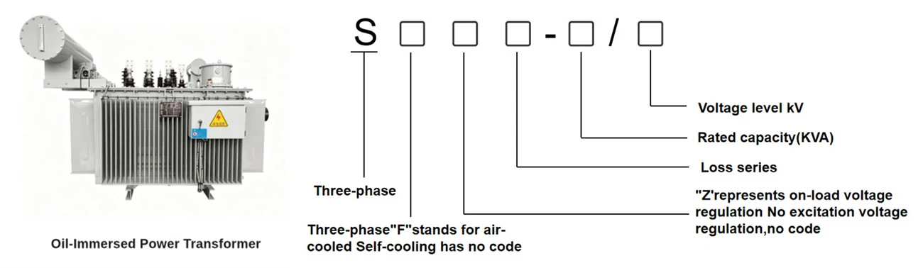
Main Parameters
|
Rated Power (kV) |
Vector Group |
Voltage Combination (kV) |
No-load Loss (W) |
Load Loss (W) |
No-load Current (%) |
Short-circuit Impedance (%) |
||
|
High-Voltage |
Tapping Range |
Low-Voltage |
||||||
|
2000 |
Yd11 |
35 |
±3×2.5% |
6.3 10.5 |
2300 |
19240 |
0.80 |
6.5 |
|
2500 |
2720 |
20640 |
0.80 |
|||||
|
3150 |
35~38.5 |
±3×2.5% |
6.3 10.5 |
3230 |
24710 |
0.72 |
7.0 |
|
|
4000 |
3870 |
29160 |
0.72 |
|||||
|
5000 |
4640 |
34200 |
0.68 |
|||||
|
6300 |
5630 |
36800 |
0.68 |
7.5 |
||||
|
8000 |
Ynd11 |
35~38.5 |
±3×2.5% |
6.3 6.6 10.5 11 |
7870 |
40600 |
0.60 |
|
|
10000 |
9280 |
48100 |
0.60 |
|||||
|
12500 |
10940 |
56900 |
0.56 |
8.0 |
||||
|
16000 |
13170 |
70300 |
0.54 |
|||||
|
20000 |
15570 |
82800 |
0.54 |
|||||
Note: For transformers with low-voltage voltages of 10.5kV and 11kV, products with connection group number Dyn11 can be provided.
Environment
|
Item |
Requirement |
|
Ambient temperature |
Max. +40℃, min. -30℃ (low-temperature special insulating oil available for cold regions) |
|
Altitude |
≤ 1000m (above 1000m: reinforced insulation and derated temperature rise) |
|
Relative humidity |
Monthly average ≤ 90%, no condensation (anti-corrosion tank for coastal salt-fog areas) |
|
Installation site |
Outdoor open-air substations, indoor distribution rooms; no explosion hazard, corrosive gas or heavy dust |
|
Seismic intensity |
≤ 8 degrees (vibration-damping base optional) |
Application
Urban & Rural Power Grid Substation
SZ‑series on‑load regulating transformers serve 35kV regional substations and rural grid renovation projects. Frequent voltage swing occurs between peak and off‑peak load periods. With uninterrupted on‑load tap adjustment, the transformer stabilizes distribution network voltage, mitigates over‑voltage and under‑voltage issues, and enhances overall power‑supply reliability.
Renewable Energy Power Station
Suitable for PV plants, wind farm booster stations and energy‑storage facilities. Intermittent power output from solar and wind sources causes continuous voltage drift. The OLTC function dynamically compensates voltage deviation, ensuring stable power delivery to the grid and meeting grid‑connection requirements.
Heavy‑Duty Industrial Site
Deployed in metallurgy, chemical, mining and large‑scale industrial parks. Heavy and sharply‑changing loads bring obvious voltage fluctuation. On‑load voltage regulation maintains steady secondary voltage, protects production equipment and avoids unexpected shutdown for continuous‑process manufacturing.
Critical Infrastructure
Ideal for data centers, hospitals, airports and railway power supply systems. These facilities demand high‑quality, uninterrupted power supply. SZ transformers correct grid voltage variations in real time, preventing equipment damage and business loss caused by voltage abnormality.
OLTC (On‑Load Tap‑Changer) Structure Description
Based on assembly drawing for SZ‑series transformer.
Main Components
Motor Drive Unit
Mounted on top of OLTC tank. Provides mechanical power for tap position change, includes position indicator for tap signal feedback.
OLTC Main Tank (Independent Oil Compartment)
Separate oil chamber for switching contacts. All arcing during tap change happens inside this tank, isolated from main transformer oil.
Transformer Mounting Flange
Large sealing flange with M16 bolts. Fastens the whole OLTC onto transformer cover, provides oil‑tight sealing between OLTC chamber and transformer tank.
Tap Terminal Connections (A', B' terminals)
External tap terminals, connect to high‑voltage winding tap leads of transformer.
Pressure Relief Device
Safety fitting on OLTC tank bottom. Releases over‑pressure generated by internal fault to avoid tank damage.
Oil Inlet & Oil Outlet Nozzles
Pipe connections for external oil filter unit. Permits independent oil circulation and purification for OLTC compartment. Matching mounting flange for pipe connection.
Top Flange Assembly (Φ570)
• Gear starting position: Mechanical reference mark for tap commissioning
• Controlling cable socket: Electrical connection for motor power and tap‑position signal
• Rating plate: Nameplate of OLTC
• Oil inlet / outlet pipe connections
Arc‑risk Zone (B‑B View, Φ490 Range)
Internal working area where switching arc occurs. Foreign objects are prohibited within this zone during installation and maintenance.
Internal Contact System (Neutral‑point Tap‑change Principle)
Three‑phase tap contacts inside tank. Tap switching is performed at winding neutral point. Low‑voltage stress for OLTC, suitable for YNd11 35kV SZ transformers. Realizes on‑load voltage adjustment without power interruption.

Proccess of Transformer
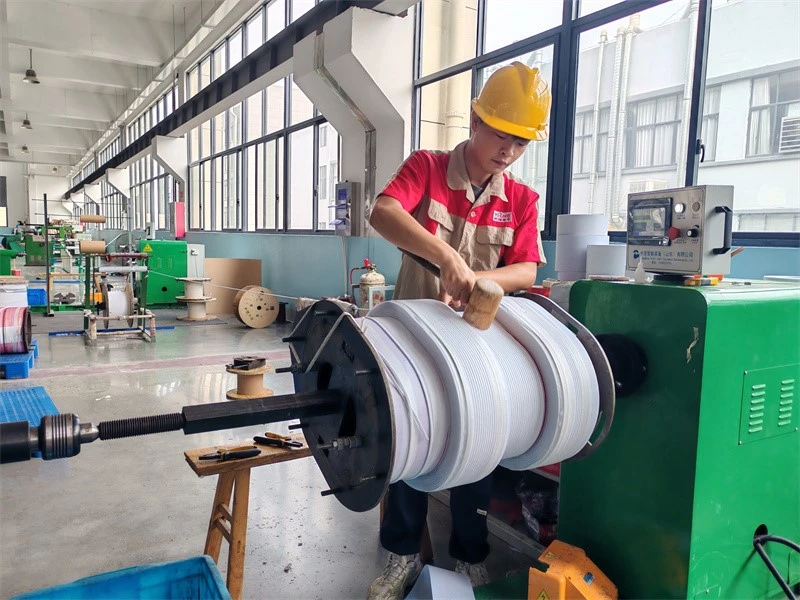
1-Wire‑wound winding of transfomer
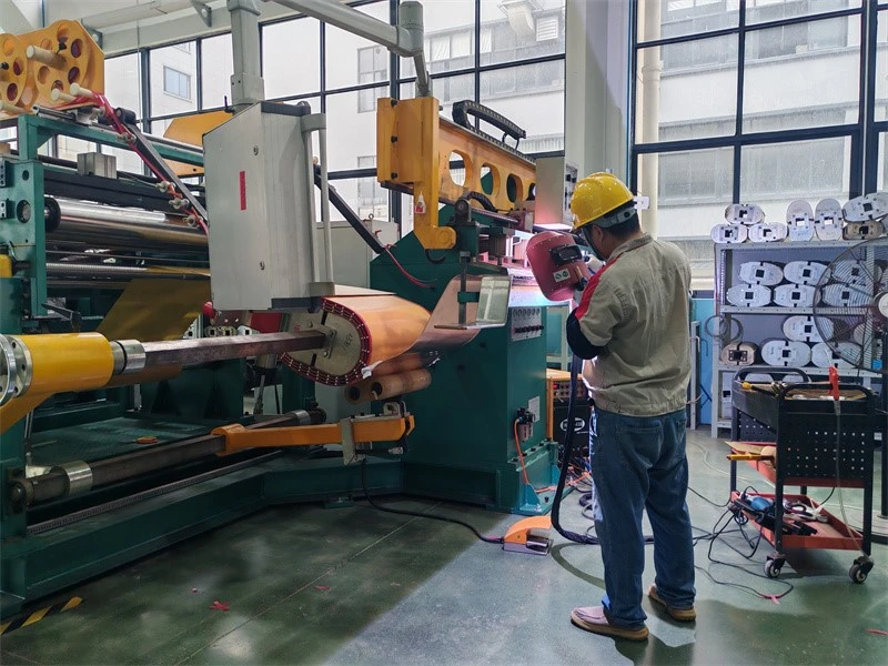
2-Foil‑wound winding of transfomer
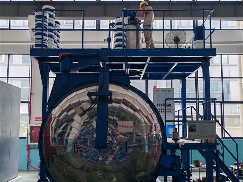
3-Vacuum casting of transformer
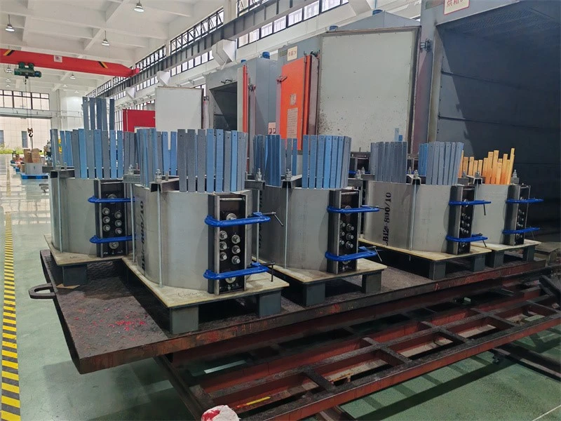
4-Epoxy resin casting of transfomer
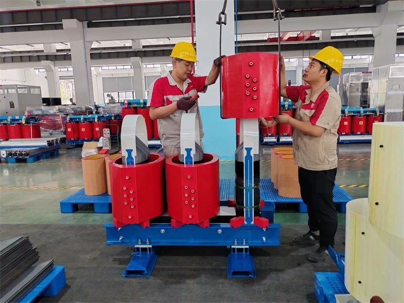
5-Coil assembling over core
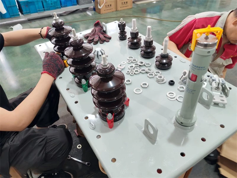
6-HV porcelain bushings of oil immersed transformer
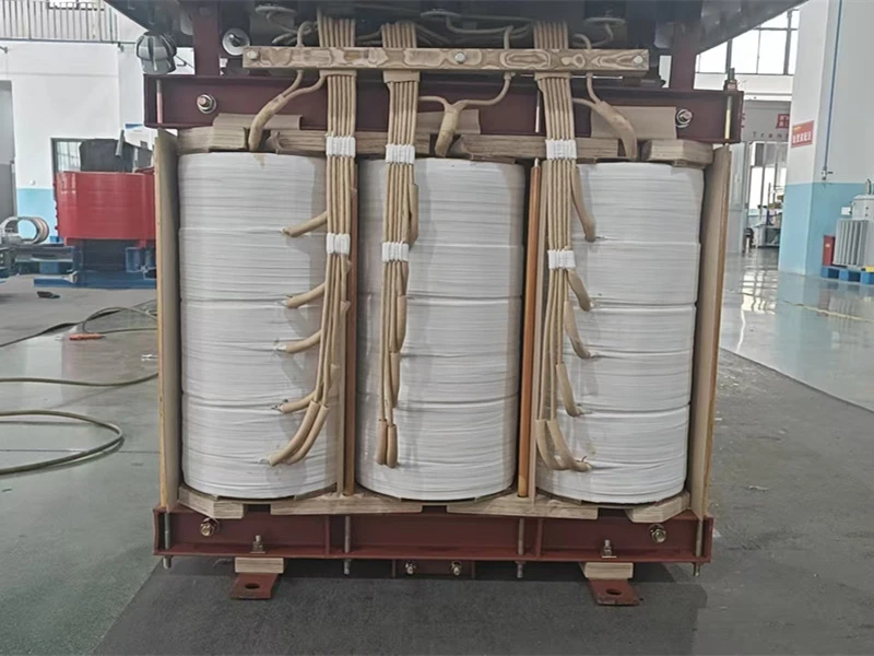
7-Lead insulation taping and welding of transfomer
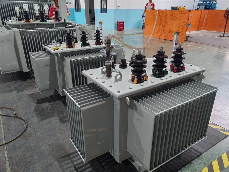
8-Vacuum oil filling of transformer
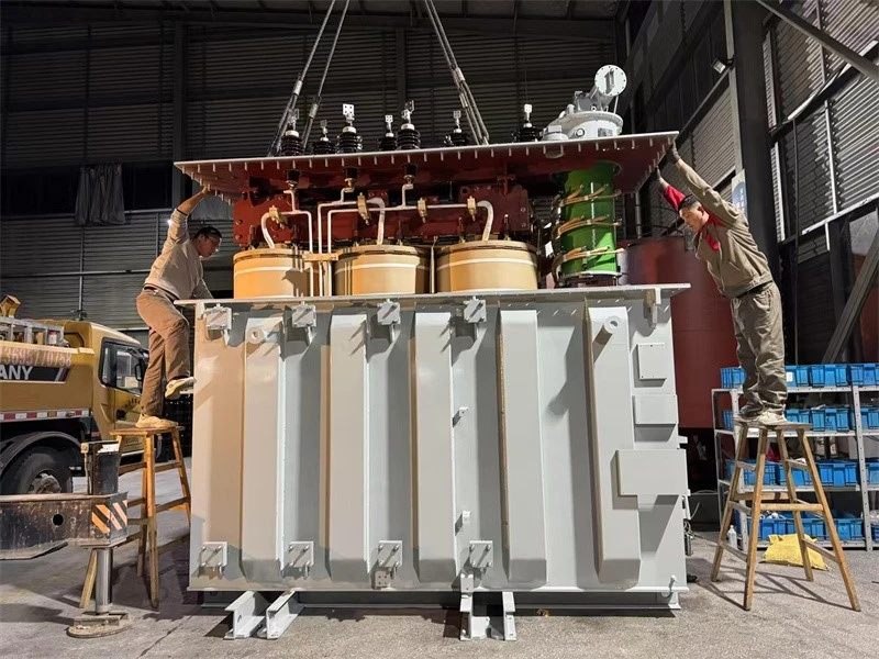
9-Tank sealing of transformer
Testing of Transformer
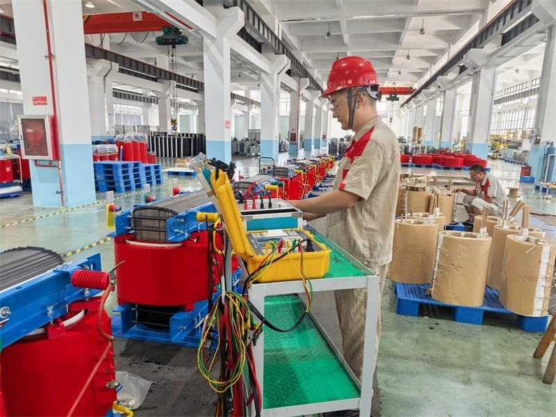
1-Measurement of winding resistance testing of transformer
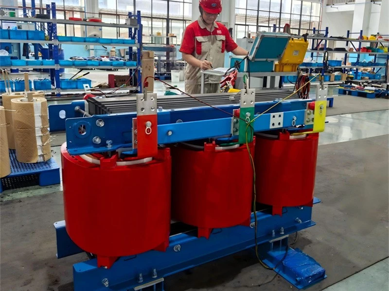
2-Measurement of voltage ratio and check of phase displacement testing of transformer
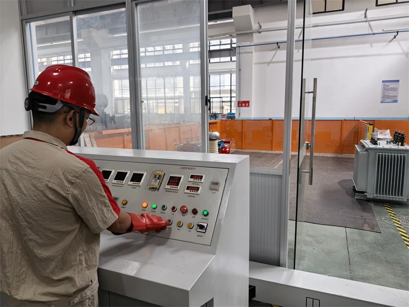
3-Separate‑source AC withstand voltage testing of transformer
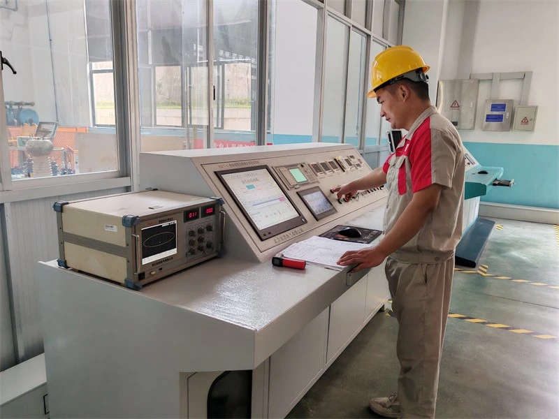
4-Measurement of no‑load loss and no‑load current of transformer
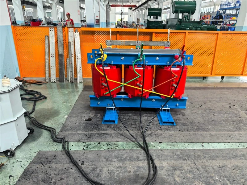
5-Measurement of short‑circuit impedance and load loss of transformer
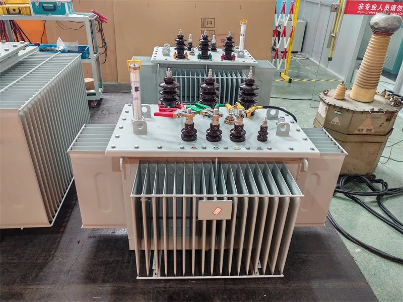
6-No load loss and no load current testing of transformer
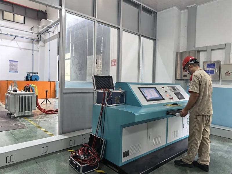
7-Temperature‑rise test of transformer
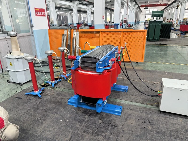
8-Partial‑discharge measurement of transformer
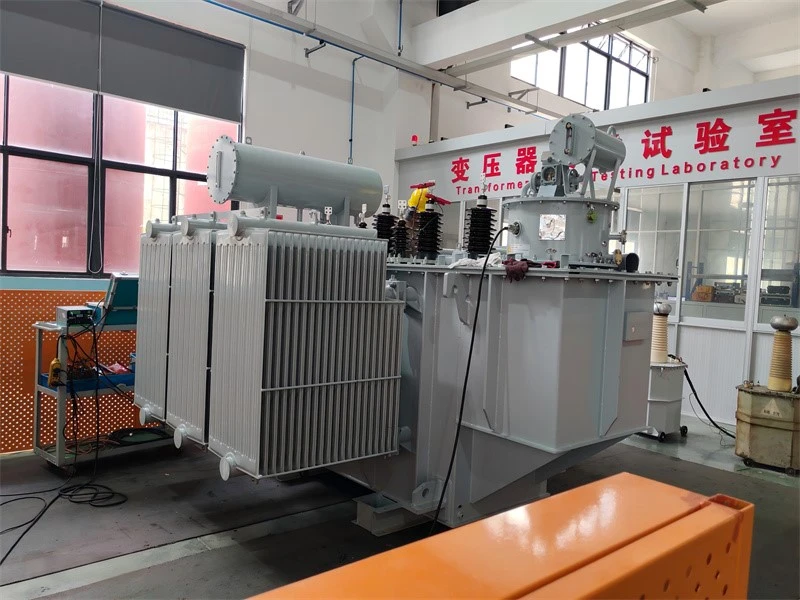
9-Winding ressitant and voltage ratio testing of transformer
FAQ
Q1: What is OLTC?
A: OLTC (On-Load Tap Changer) is a built-in device that adjusts transformer voltage without power cut and under full load, keeping output voltage stable during grid fluctuation.
Q2: What is the working principle of OLTC?
A: It uses transition resistors to complete tap switching instantly. The load current is never interrupted. Tap changing is performed at the HV neutral point with low voltage stress, and switching arcs are isolated in an independent oil chamber.
Q3: What scenarios need OLTC transformers?
A: Sites with frequent grid voltage fluctuation, including power substations, renewable energy stations, continuous-production factories and critical infrastructure.
Hot Tags: on-load tap changer distribution voltage regulators, China on-load tap changer distribution voltage regulators manufacturers, suppliers, factory
You Might Also Like
Send Inquiry