


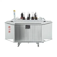
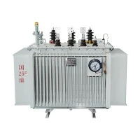
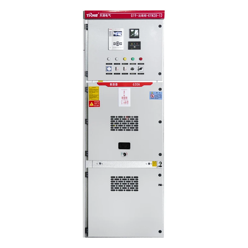

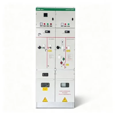
Armoured Middle-Mounted Metal Enclosed High Voltage Switchgear
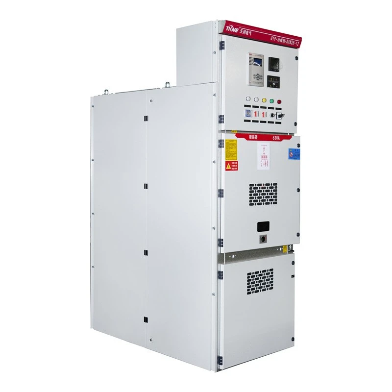
Armoured Middle-Mounted Metal Enclosed High Voltage Switchgear suppliers
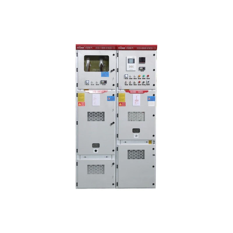
Armoured Middle-Mounted Metal Enclosed High Voltage Switchgear factory
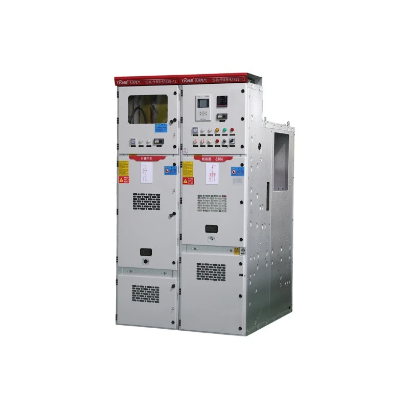
Armoured Middle-Mounted Metal Enclosed High Voltage Switchgear best
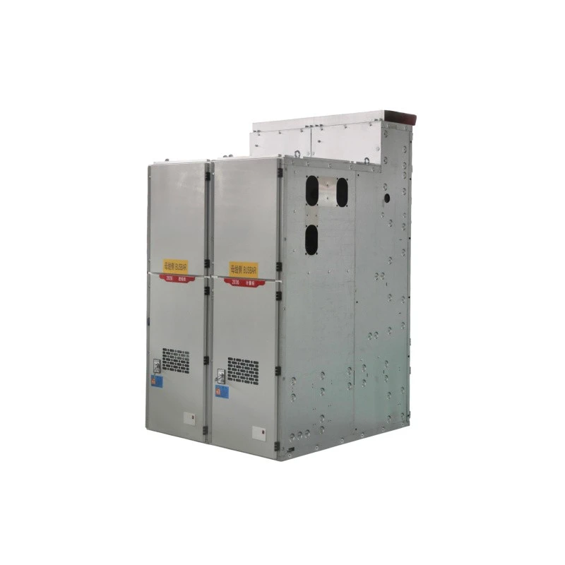
Armoured Middle-Mounted Metal Enclosed High Voltage Switchgear high quality
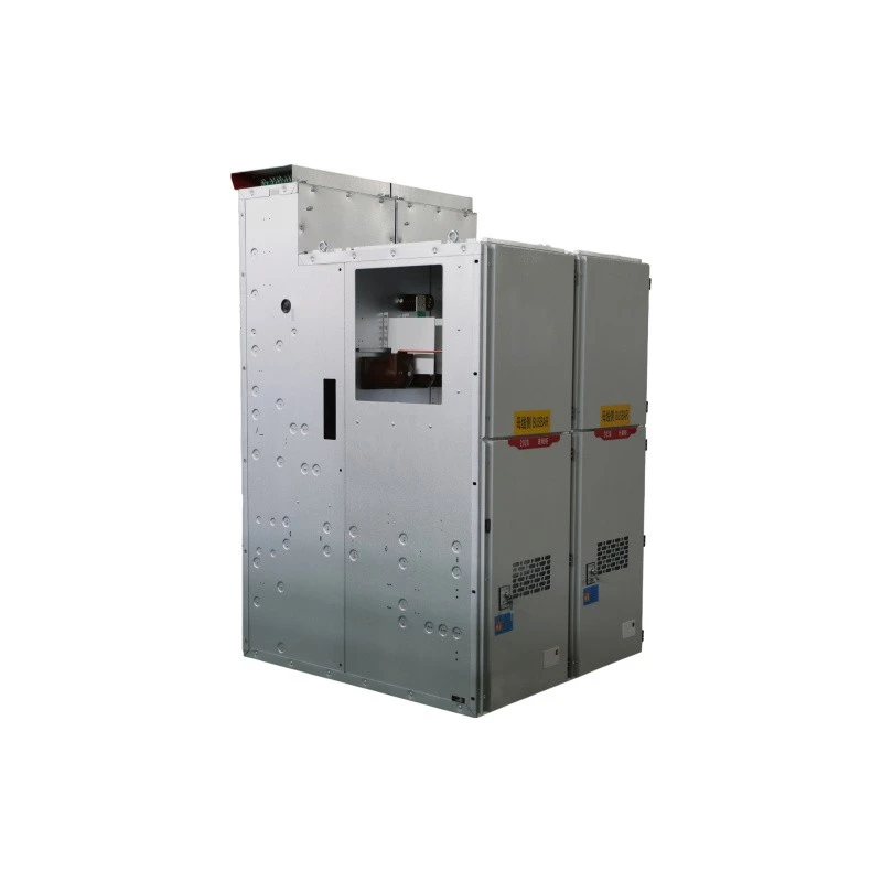
Armoured Middle-Mounted Metal Enclosed High Voltage Switchgear price
Armoured Middle-Mounted Metal Enclosed High Voltage Switchgear
Rated Voltage: 3.6 / 7.2 / 12 kV (Customized)
Rated Frequency: 50 Hz (Customized)
Rated Current: 630 – 3150 A (Customized)
Rated Short-Circuit Breaking Current: 16 – 50 kA
Protection Class: IP4X (main enclosure) / IP2X (internal compartments)
Standards: IEC 62271-200, IEC 62271-1, IEC 62271-100
Zhejiang Tianrun Electric Co., Ltd. is one of the leading manufacturers and suppliers of armoured middle-mounted metal enclosed high voltage switchgear in China. We are committed to providing high quality customized products with competitive price. We warmly welcome you to buy bulk advanced armoured middle-mounted metal enclosed high voltage switchgear from our factory. Also, quotation is available.
Product Overview
KYN28-12 indoor AC metal-enclosed high voltage switch cabinet is designed for 3.6–12 kV three-phase AC 50 Hz single-busbar systems. It is used for generator power supply, industrial and mining distribution, substation reception and distribution, and high-voltage motor control and protection. Compliant with GB3906-2006, this high voltage switch cabinet delivers high reliability, safety, and operational stability.

Core Features
Outstanding Performance
KYN28-12 belongs to high-performance medium-voltage distribution equipment with:
- High breaking capacity and operational stability
- Compact structure and convenient maintenance
- Long mechanical and electrical lifespan - Excellent insulation and heat dissipation performance
Strong Compatibility
The switchgear supports flexible configuration with mainstream circuit breakers:
- Domestic models: VS1 series vacuum circuit breakers from major domestic manufacturers
- International models: ABB VD4 series vacuum circuit breakers It ensures high interchangeability and meets diverse project configuration requirements.
Structural Features
- Armoured metal-enclosed structure: High mechanical strength and protection level
- Middle-mounted with drawable trolley: Easy for inspection, maintenance, and replacement
- Compartmentalized design: Independent chambers for circuit breaker, busbar, cable, and instrument
- Protection class: IP4X for main enclosure, IP2X for internal compartments
- Flexible installation: Can be single-sided, back-to-back, or wall-mounted
Five Anti-Misoperation Interlocking Functions
The switchgear is equipped with perfect mechanical & electrical interlocks to realize complete "Five Prevention" capabilities:
- Prevent pushing or pulling the circuit breaker trolley under load
- Prevent misoperation (erroneous closing/opening) of the circuit breaker
- Prevent closing the grounding switch when the circuit breaker is in closed position
- Prevent unauthorized entry into live compartments
- Prevent closing the grounding switch when the circuit is energized
Main Technical parameters
|
Rated Voltage (kV) |
03/6/10 |
||||
|
Maximum Operating Voltage (kV) |
3.6/7.2/12 |
||||
|
Power Frequency Withstand Voltage (kV) |
42 (1 min) |
||||
|
Impulse Withstand Voltage (kV) |
75 |
||||
|
Rated Frequency |
50Hz |
||||
|
Rated Current (A) |
630-3150 |
||||
|
Rated Thermal Stability Current (kA/4s) |
16-50 |
||||
|
Rated Dynamic Stability Current (kA) |
40-125 |
||||
|
Rated Short-Circuit Breaking Current (kA) |
16-50 |
||||
|
Rated Short-Circuit Making Current (kA) |
40-125 |
||||
|
Rated DC Voltage for Opening / Closing Switch and Auxiliary Circuits |
24, 30, 48, 60, 110, 220, AC110, 220 |
||||
|
Protection Class |
IP4X |
||||
|
△ Technical data for VSI and VD4 vacuum circuit breakers are shown in the table below: |
|||||
|
Items |
Unit |
VSI |
VD4 |
||
|
Rated Voltage |
kV |
3 6 |
10 |
||
|
Maximum Operating Voltage |
kV |
3.6 7.2 12 |
|||
|
Rated Insulation |
Power Frequency Withstand Voltage for 1 minute |
kV |
42 |
||
|
Level |
Lightning Impulse Withstand Voltage |
kV |
75 |
||
|
Rated Frequency |
Hz |
50 |
|||
|
Rated Current |
A |
630, 1250, 1600, 2000, 2500, 3150 |
|||
|
Rated Short-Circuit Breaking Current (RMS) |
kA |
16, 20, 25, 31.5, 40, 50 |
|||
|
4S Thermal Stability Current (RMS) |
kA |
16, 20, 25, 31.5, 40, 50 |
|||
|
Rated Dynamic Stability Current (Peak) |
kA |
40, 50, 63, 80, 100, 125 |
|||
|
Transient Recovery Voltage Rate |
kV/ms |
0.345 |
0.415 |
||
|
Peak Transient Recovery Voltage |
kV |
20.6 |
30 |
||
|
Rated Operation Sequence |
O-0.3S-CO-180S-CO |
||||
|
Automatic Reclosing Operation Sequence |
O-0.3S-CO-3min-CO |
||||
|
Multiple Reclosing Operation Sequence |
O – 0.3 s – CO – 15 s – CO – 15 s – CO |
||||
|
Closing Time |
ms |
100 |
70 |
||
|
Opening Time |
ms |
20 |
45 |
||
|
Arcing Time |
ms |
15 |
15 |
||
|
Breaking Time |
ms |
65 |
60 |
||
|
|
The schematic diagram of the switchgear structure A. Busbar Compartment B. Circuit Breaker Trolley Compartment D. Relay and Instrument Compartment 1.1 Pressure Relief Device 1. Enclosure 2. Branch Busbar 3. Busbar Sleeve 4. Main Busbar 5. Static Contact Device 7. Current Transformer 8. Grounding Switch 10. Surge Arrester 11. Grounding Main Busbar 13. Partition (Live Door) 15. Circuit Breaker Trolley 17. Withdrawable Horizontal Partition 18. Grounding Switch Operating Mechanism |
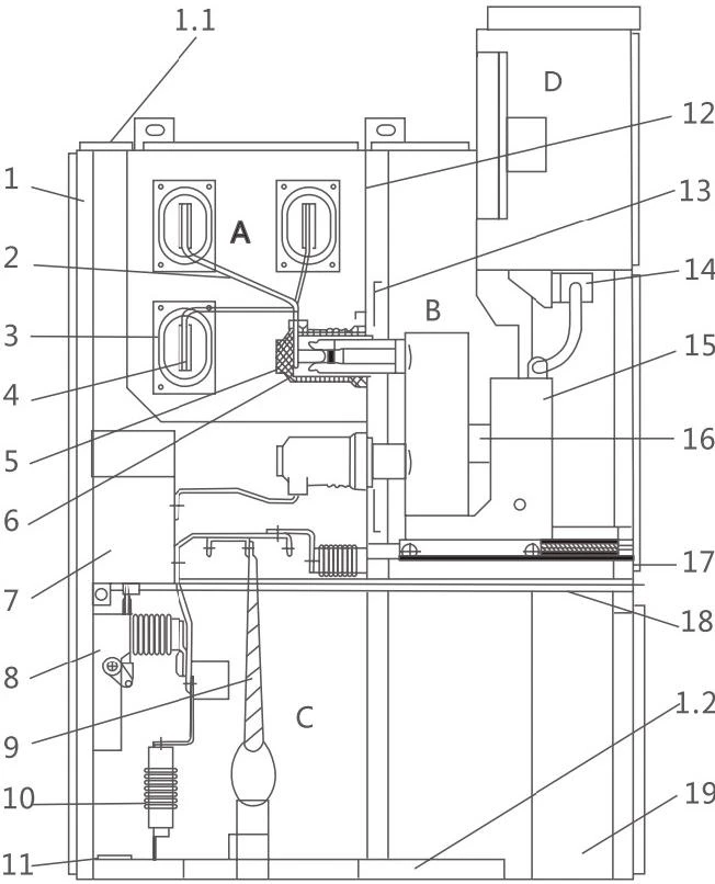
|
The Outline Dimensions of the Switchgear |
|
* For Rated Currents Exceeding 1600A, the Dimension is 1000mm; for others, it is 800mm |
|
** Cable Inlet and Outlet Dimensions: 1500mm for overhead Lines and 1660mm for Overhead Lines |
|
|

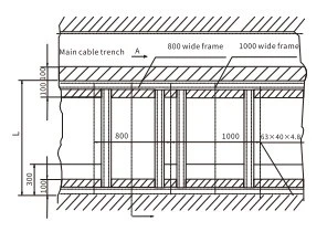
Switchgear Base Installation Diagram
|
Cabinet Width |
Cabinet Depth |
M |
N |
L |
|
|
800 |
1500 Cable |
630 |
800 |
1450 |
|
|
1660 Overhead |
1610 |
||||
|
1000 |
1500 Cable |
830 |
1000 |
1450 |
|
|
1660 Overhead |
1610 |

Switchgear Installation Dimension Diagram
|
Cabinet Width |
Cabinet Depth |
L1 |
L2 |
L3 |
|
|
800 |
1500 Cable |
530 |
630 |
800 |
|
|
1660 Overhead |
|||||
|
1000 |
1500 Cable |
730 |
830 |
1040 |
|
|
1660 Overhead |

Switchgear Installation Dimension Diagram
|
|
Cabinet Depth |
L |
|
1500 |
1450 |
|
|
1660 |
1610 |
Operating Environment Conditions
Normal Conditions
- Ambient Air Temperature: Upper limit +40℃, lower limit -10℃
- Altitude: ≤1,000 meters
- Relative Humidity: Daily average ≤95%, monthly average ≤90%
- Seismic Intensity: Not exceeding 8°
- Surrounding Air: Free from corrosive, flammable gases, excessive water vapor, or significant contaminants
- Vibration & Pollution: No severe pollution or frequent intense vibrations
- Harsh Environment Design: Must meet Class 1 requirements
Special Conditions
When used under environmental conditions exceeding those specified in GB3906-2006, the user and manufacturer shall negotiate customized solutions and technical parameters.
Application Scenarios
Power plants (small/medium generator power supply), industrial and mining enterprises (power distribution), secondary substations (power reception/distribution), large high-voltage motor start control/protection/monitoring.
Selection Guide
- General Power Distribution: 10kV, 1250A, 31.5kA (residential areas, malls, office buildings, general factories).
- Industrial/Heavy Load/Motor Start: 1600A/2000A, 40kA (mines, metallurgy, chemical industry, large high-voltage motors).
- Power Plants/Key Substations: 2500A~3150A, 50kA (main transformer incoming line, bus tie, key power circuits).
FAQ
Q1: Which circuit breakers can be installed?
A: The switchgear is compatible with domestic VS1 series vacuum circuit breakers and imported ABB VD4 series vacuum circuit breakers, ensuring high interchangeability.
Q2: Which international standards does it comply with?
A: IEC 62271-200 (AC metal-enclosed switchgear), IEC 62271-1 (common specifications), and IEC 62271-100 (AC circuit-breakers).
Q3: What installation arrangements are supported?
A: The switchgear supports single-sided arrangement, back-to-back arrangement, and wall-mounted installation, offering flexibility for different substation layouts.
Hot Tags: armoured middle-mounted metal enclosed high voltage switchgear, China armoured middle-mounted metal enclosed high voltage switchgear manufacturers, suppliers, factory
You Might Also Like
Send Inquiry