


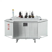
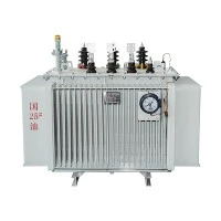
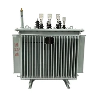
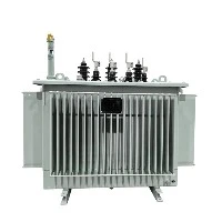
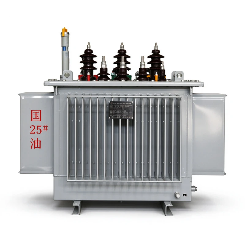

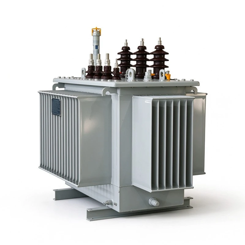
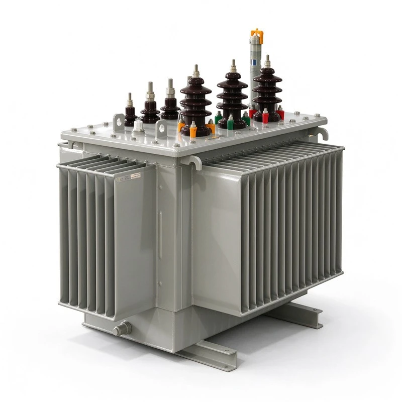
S Series Oil Immersed Step Up Transformer Suit New Energy
Zhejiang Tianrun Electric Co., Ltd. is one of the leading manufacturers and suppliers of s series oil immersed step up transformer suit new energy in China. We are committed to providing high quality customized products with competitive price. We warmly welcome you to buy bulk advanced s series oil immersed step up transformer suit new energy from our factory. Also, quotation is available.
Product Overview
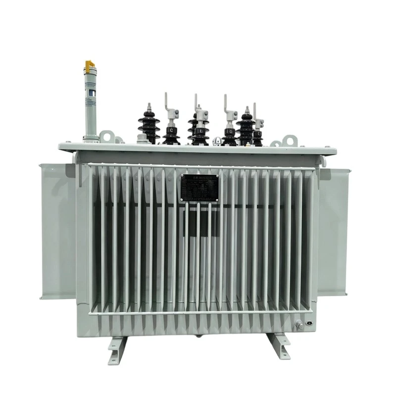
The S series are three-phase, oil-immersed step-up transformers for grid connection of photovoltaic plants, wind farms and energy storage stations. They step up the low-voltage output of inverters or PCS units (0.4 kV, 0.8 kV, 1.14 kV, etc.) to grid voltage levels of 10 kV, 20 kV or 35 kV. Design and manufacture follow GB/T 6451-2023 (Specification and technical requirements for oil-immersed power transformers) and the GB/T 1094 series, which correspond to the IEC 60076 series.
The parameters listed in this catalog are typical values. Final specifications are subject to the technical agreement.

Product Features
Construction Design
Spiral windings with longitudinal oil ducts - the ducts take part in cooling directly and help even out the temperature distribution inside the winding.
Effective end support of the windings improves their stability under short-circuit forces.
Dedicated lifting and core-positioning arrangements reduce the risk of displacement or damage during long-distance transport.
Fully sealed tank isolates the transformer from the atmosphere, slowing oil aging and insulation moisture ingress; no routine maintenance is required during normal operation.
Materials
Oxygen-free copper conductors, surface-treated to remove burrs and sharp edges; a smoother conductor surface helps control load loss.
Grain-oriented silicon steel with low specific loss - the grade is selected according to the performance level to control no-load loss.
Insulation parts made of laminated wood and similar materials, with stable mechanical strength and good resistance to cracking.
Transformer oil is deep-filtered to control moisture, gas and impurity content for more reliable operation.
Aging-resistant rubber sealing elements, combined with the fully sealed tank, minimize the risk of leakage.
All raw materials and their suppliers are reviewed against the ISO 9000 quality management system requirements, and incoming materials are used only after passing inspection.
Type Designation

Structure Features

Technical Parameter
|
Item |
Value |
|
Rated frequency |
50 Hz |
|
Phases |
3 |
|
Cooling method |
ONAN (oil-immersed, self-cooled) |
|
Vector group |
10 kV distribution: Dyn11 / Yzn11 / Yyn0; 10 kV power: Yd11; 35 kV distribution: Dyn11 / Yyn0; 35 kV power: Yd11 / YNd11 (Dyn11 also available for 10.5 kV LV) |
|
Tap changer |
Off-circuit (OLTC on request) |
|
Tapping range |
±2×2.5%, ±5% available |
|
Insulation levels |
10 kV class (Um=12 kV): LI 75 kV / AC 35 kV; 35 kV class (Um=40.5 kV): LI 200 kV / AC 85 kV (per GB/T 1094.3-2017) |
|
Temperature rise limits |
Average winding 65 K, top oil 60 K (per GB/T 1094.2-2013) |
|
Sound level |
Measured per GB/T 1094.10-2022; limits per GB/T 6451-2023 / JB/T 10088 |
|
Transformer oil |
Mineral insulating oil (GB 2536-2025); high-flash-point oil optional |
|
Altitude |
≤1000 m; corrected per GB/T 1094.1 for higher altitudes |
|
Ambient temperature |
-25 ℃ to +40 ℃ |
|
Protection devices |
Pressure relief valve, oil level gauge, temperature indicator; Buchholz relay recommended ≥800 kVA, otherwise on request |
Environment Condition
• Altitude: not exceeding 1000m
• Ambient temperature:
Maximum ambient temperature: +40℃
Average temperature of the hottest month: +30℃
Maximum annual average temperature: +20℃
Outdoor minimum temperature: -25℃
• Supply voltage: the waveform shall be approximately sinusoidal
For three-phase transformers, the three-phase supply voltages shall be approximately symmetrical.
• Installation site: no obvious pollution (pollution class to be determined per the applicable standard and site conditions).
• Seismic resistance: ground acceleration - horizontal ≤ 3 m/s², vertical ≤ 1.5 m/s².
• Special conditions of use: any condition outside the range above shall be stated at the time of inquiry and order.
Application
Photovoltaic Plants
Centralized PV: step-up inside skid-mounted or prefabricated substations, commonly 0.4/0.8 kV to 35 kV, feeding the collection lines to the substation.
Distributed PV: step-up to 10 kV for local grid connection.
The LV side is selected per the inverter output: 0.4/0.8/1.14 kV.
Wind Farms
Onshore: unit substations, 690 V or 0.4 kV stepped up to 35 kV.
Offshore: used in offshore substation applications; larger capacities and higher corrosion protection are typically required.
Energy Storage Stations
Step-up after PCS output to 10 kV or 35 kV.
Suitable for peak shaving, frequency regulation and other grid-connected storage applications.
Other Distributed Generation
Grid-connection step-up for small hydropower, biomass and similar distributed generation units.
★ Selection notes: rated capacity, voltage combination, impedance voltage and vector group are determined by system design; high altitude, salt fog, low temperature and other site conditions are addressed on a project basis.
Proccess of Transformer
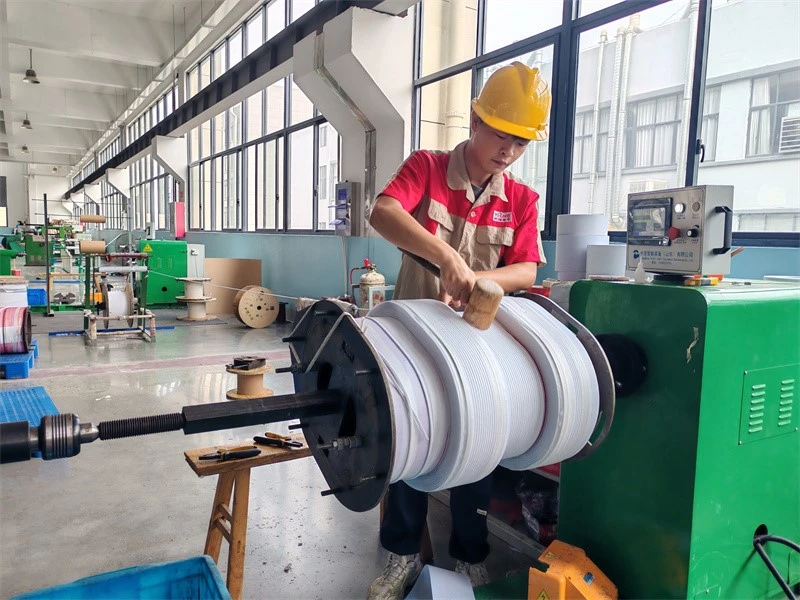
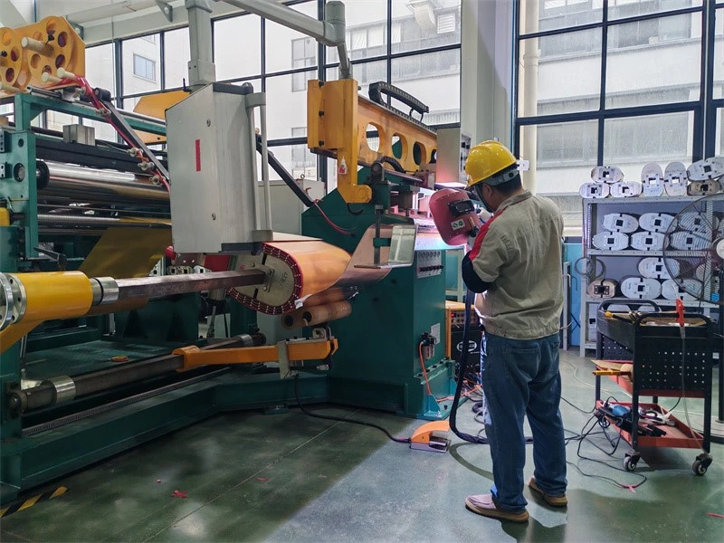
1-Wire‑wound winding of transfomer
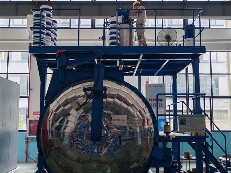
2-Foil‑wound winding of transfomer
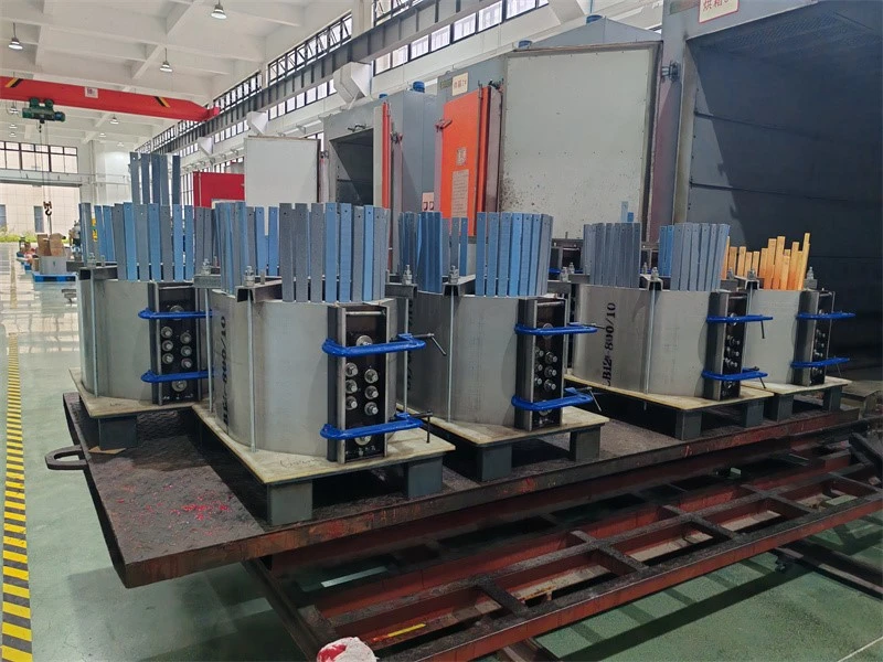
3-Vacuum casting of transformer
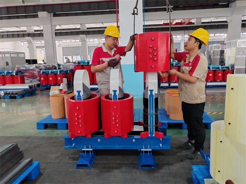
4-Epoxy resin casting of transfomer
5-Coil assembling over core
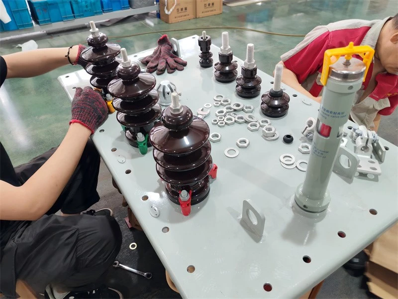
6-HV porcelain bushings of oil immersed transformer
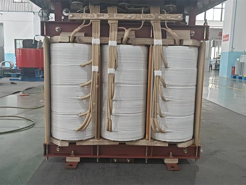
7-Lead insulation taping and welding of transfomer
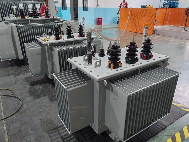
8-Vacuum oil filling of transformer
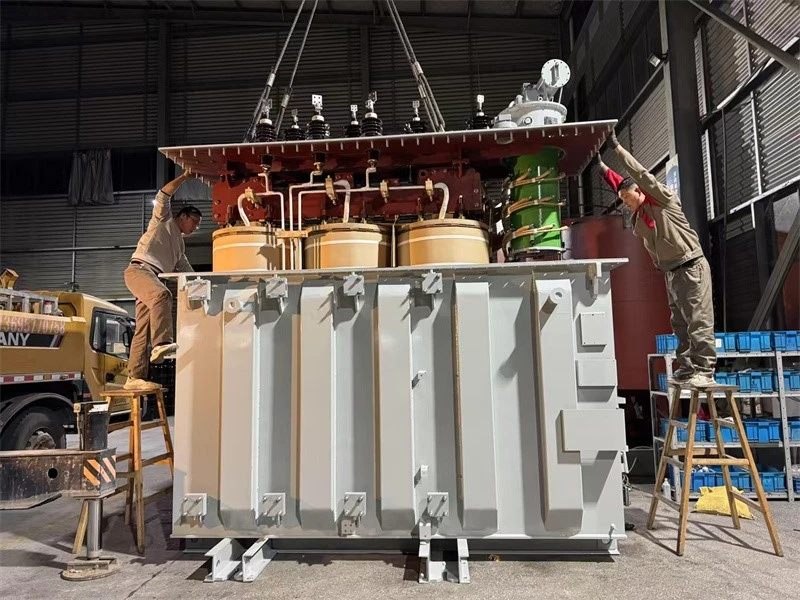
9-Tank sealing of transformer
Testing of Transformer
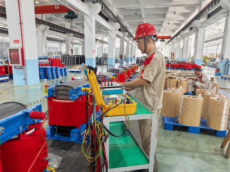
1-Measurement of winding resistance testing of transformer
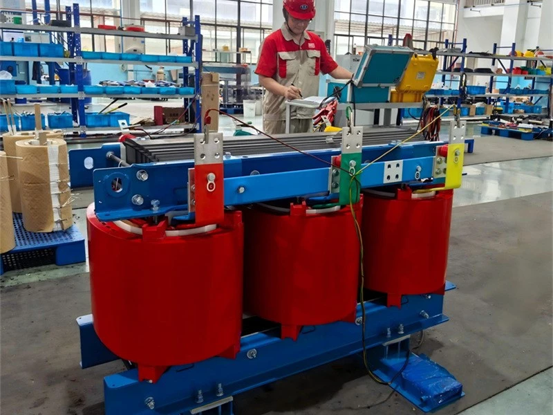
2-Measurement of voltage ratio and check of phase displacement testing of transformer
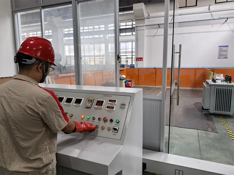
3-Separate‑source AC withstand voltage testing of transformer
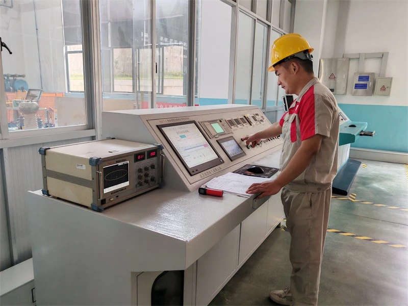
4-Measurement of no‑load loss and no‑load current of transformer
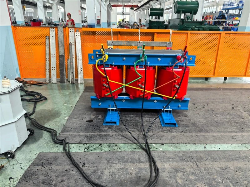
5-Measurement of short‑circuit impedance and load loss of transformer
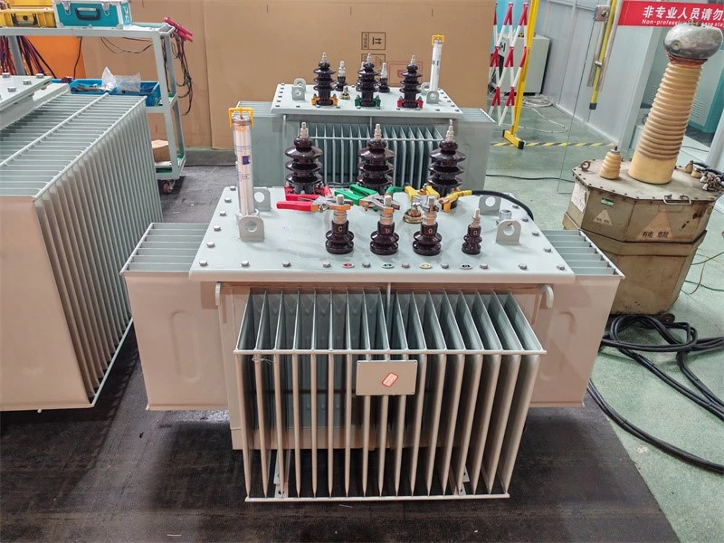
6-No load loss and no load current testing of transformer
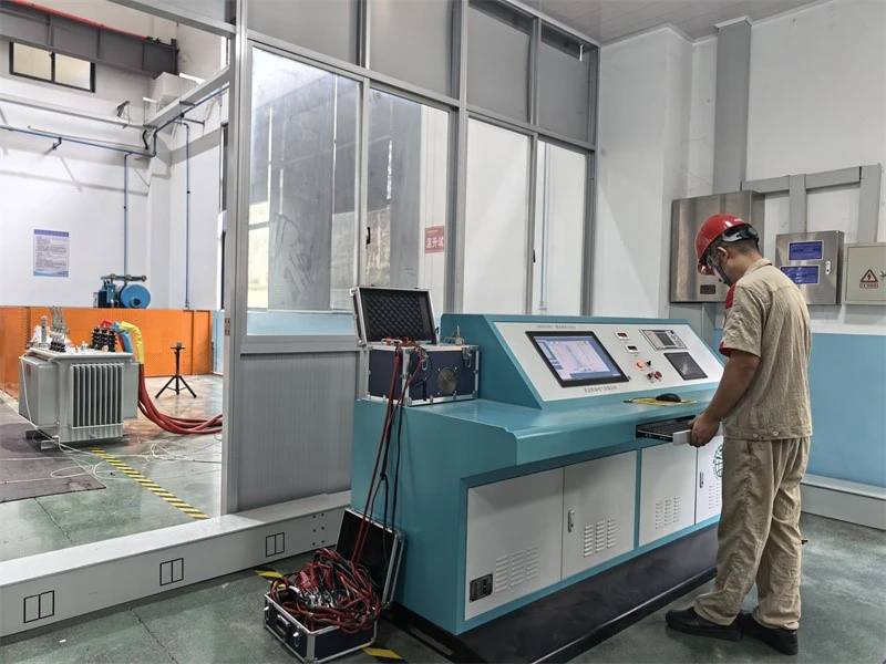
7-Temperature‑rise test of transformer
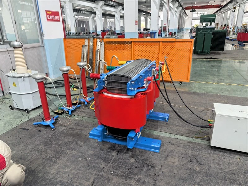
8-Partial‑discharge measurement of transformer
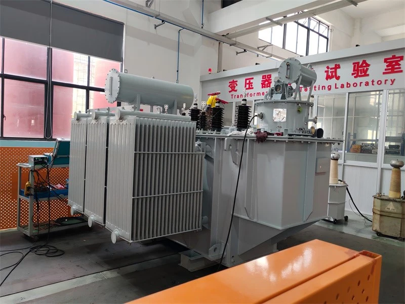
9-Winding ressitant and voltage ratio testing of transformer
FAQ
Q1: What is the purpose of a step-up transformer?
A: It raises the voltage from the low-voltage side to the high-voltage side while reducing the current accordingly. In renewable energy projects, it steps up the inverter/PCS output (0.4 kV, 0.8 kV, 1.14 kV or 690 V) to the grid voltage (10/20/35 kV). For the same power, a higher voltage means a lower current, which reduces losses and cable cross-sections on the collection network and meets the grid-connection requirements.
Q2: What is the difference between a step-down transformer and a step-up transformer?
|
Item |
Step-up transformer |
Step-down transformer |
|
Voltage |
LV → HV (increased) |
HV → LV (decreased) |
|
Current |
Decreases accordingly |
Increases accordingly |
|
Feed / supply |
Fed from LV side, supplies HV side |
Fed from HV side, supplies LV side |
|
Typical location |
Generation side, renewable grid connection |
Substations, distribution, end-user side |
|
Typical application |
PV/wind/storage step-up to 10/35 kV |
35 kV/10 kV step-down to 0.4 kV supply |
Q3: Why is it called a step-up transformer?
A: Because it steps the voltage up: power enters from the LV side and leaves at a higher voltage on the HV side, raised according to the winding turns ratio. Used in reverse, it becomes a step-down transformer.
Hot Tags: s series oil immersed step up transformer suit new energy, China s series oil immersed step up transformer suit new energy manufacturers, suppliers, factory
Previous
33kV Distribution TransformerNext
No InformationYou Might Also Like
Send Inquiry